Popp
Secure Flow Stop
SKU: POPE009501
Quickstart
This is a
Important safety information
Please read this manual carefully. Failure to follow the recommendations in this manual may be dangerous or may violate the law. The manufacturer, importer, distributor and seller shall not be liable for any loss or damage resulting from failure to comply with the instructions in this manual or any other material. Use this equipment only for its intended purpose. Follow the disposal instructions. Do not dispose of electronic equipment or batteries in a fire or near open heat sources.Product Description
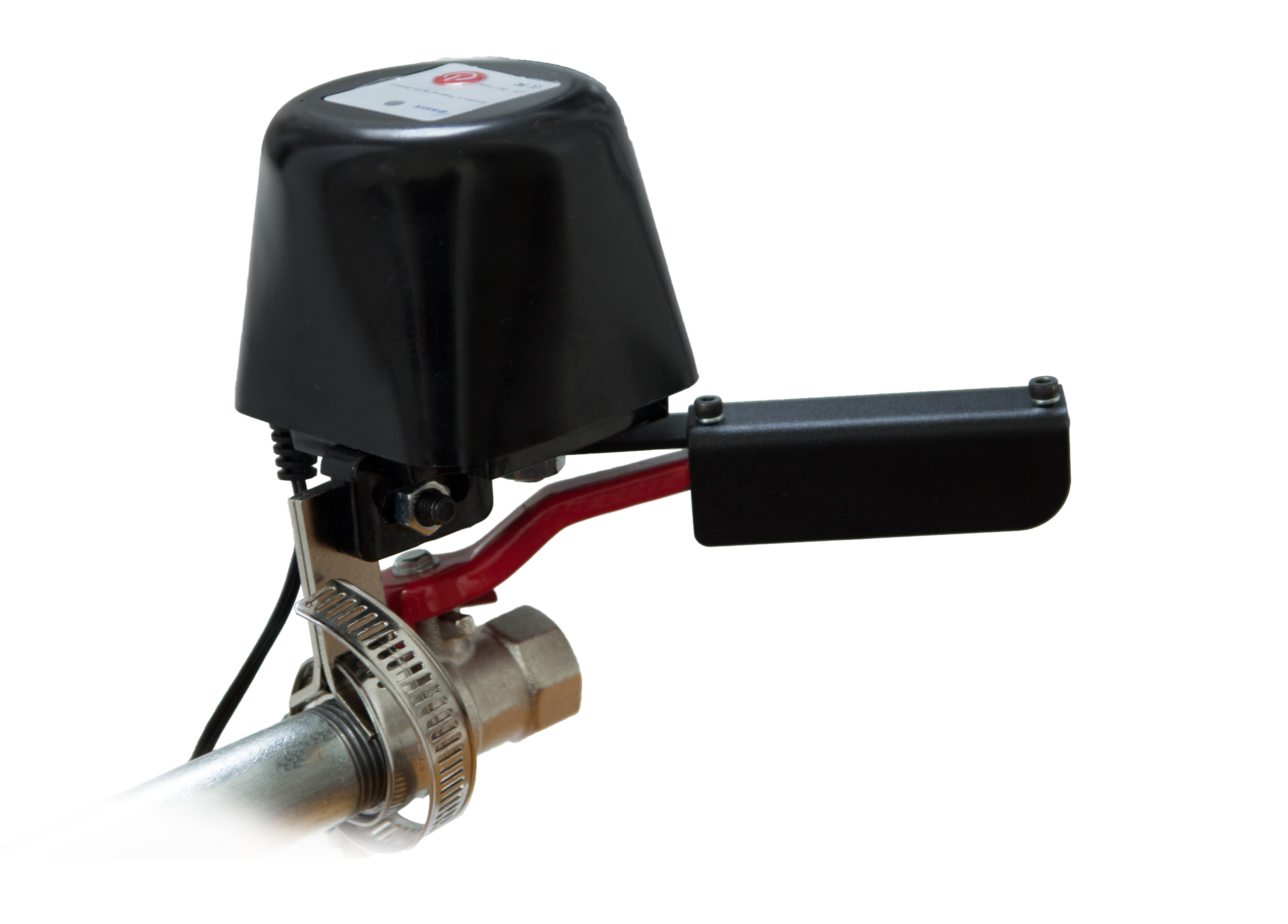
The Flow Stop moves the operating handle of a ball valve allowing to stopping the flow of gas or water. It can be mounted non-intrusive on any pipe size between 0.5 and 1.5 inch. This means the original water or gas pipe will not be opened or manipulated and it is possible to remove the Flow stop again without any damage to the water or gas pipe. Installing the Flow stop will not tamper or change any security measure applied or your gas or water installation. The device is equipped with a powerful 12 V motor providing sufficient torque to open or close any ball valve within 10 seconds. A complete manual operation of the valve remains possible due to the clutch release bearing. The device can be operated using the local button and remotely using Z-Wave wireless communication. Various functions protect the flow stop from accidental or intentional misuse:
- Z-Wave Communication applies enhanced security implementing the Security Command Class. This does not only protect the device against burglars that want to do harm to the home (e.g. waste water by opening the valve to watering system). Its also protecting better against jamming of the communication link.
- Configuration of the local LED. The user can now decide if the blue LED shall indicate open or close state
- Unsolicited report of any state change of the flow stop to the controller.
- Second communication channel to report manual operation of the device. Here up to 5 other devices can be operated independent of the controller, e.g. to announce any local operation.
- The remote operation of the device can be limited to no, only open or only close to further protect against malfunction.
Installation
Installing the Flow Stop requires some knowledge. Again there is no need to dismantle your existing installation of water or gas supply.
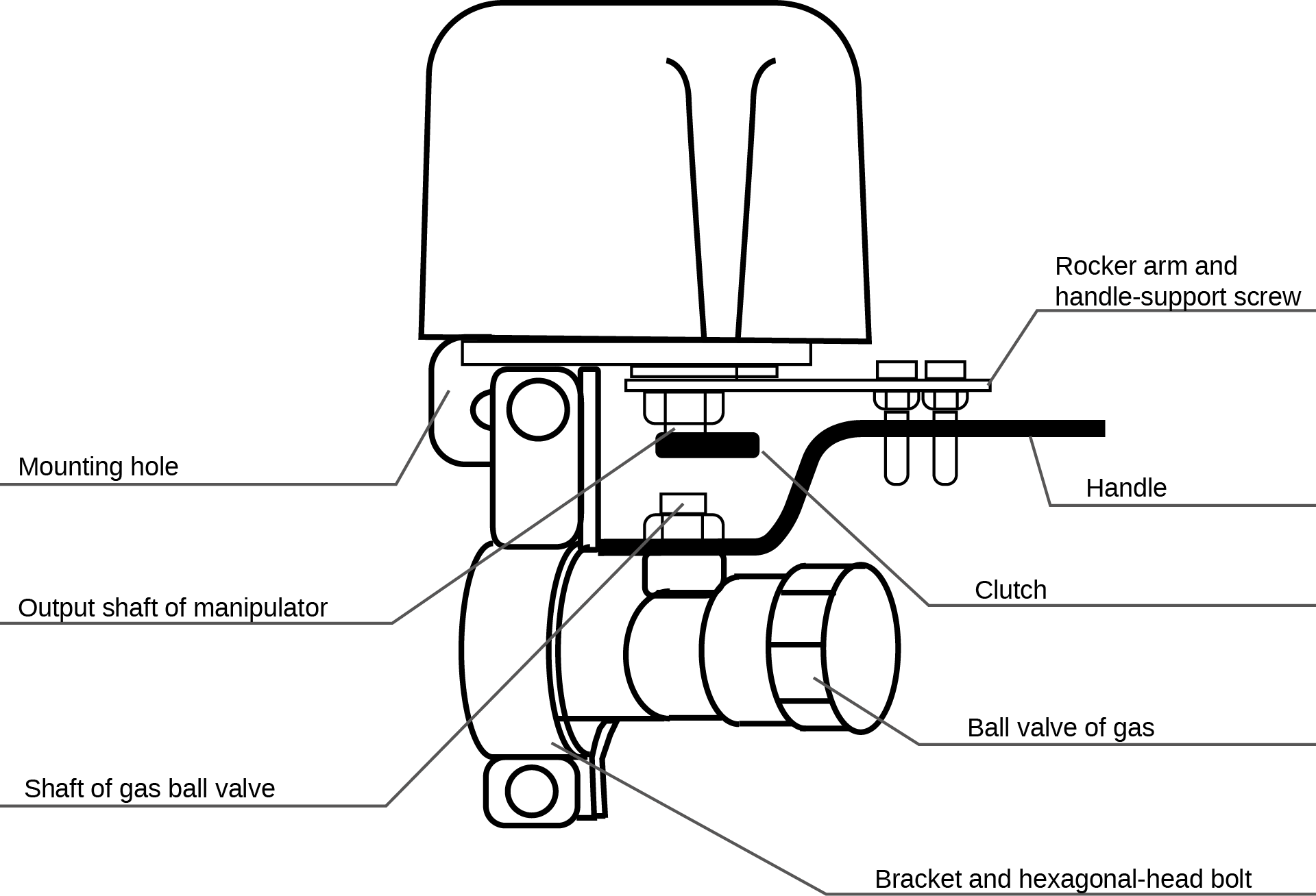
- Connect the two small mounting plate to the right and the left hand side of the mounting hole of the plastic enclosure using the screw that comes with the two minting plates. If your pipe is very thin you may want to mount them together to narrow the gap between the two angled pieces of the mounting place.
- Next you need to find the best position of the flow stop to mount. On one hand the angled parts of the mounting plates shall sit tightly on the pipe or the connecting part of the valve itself. On the other hand the rotating axis of the rocker arm needs to sit right above the rotating axis of the valve itself. Is the two rotating axis are not inline operating the flow stop electrically may damage the mechanics.
- Never move the rocker arm without disconnecting the clutch by pulling the ring on the lower side of the enclosure.
- Make sure the rotating axis of the flow stop is in line with the rotating axis of the valve. Once you found the perfect position you can tighten the two angle-shaped mounting plates to the pipe using the pipe clamp provided.
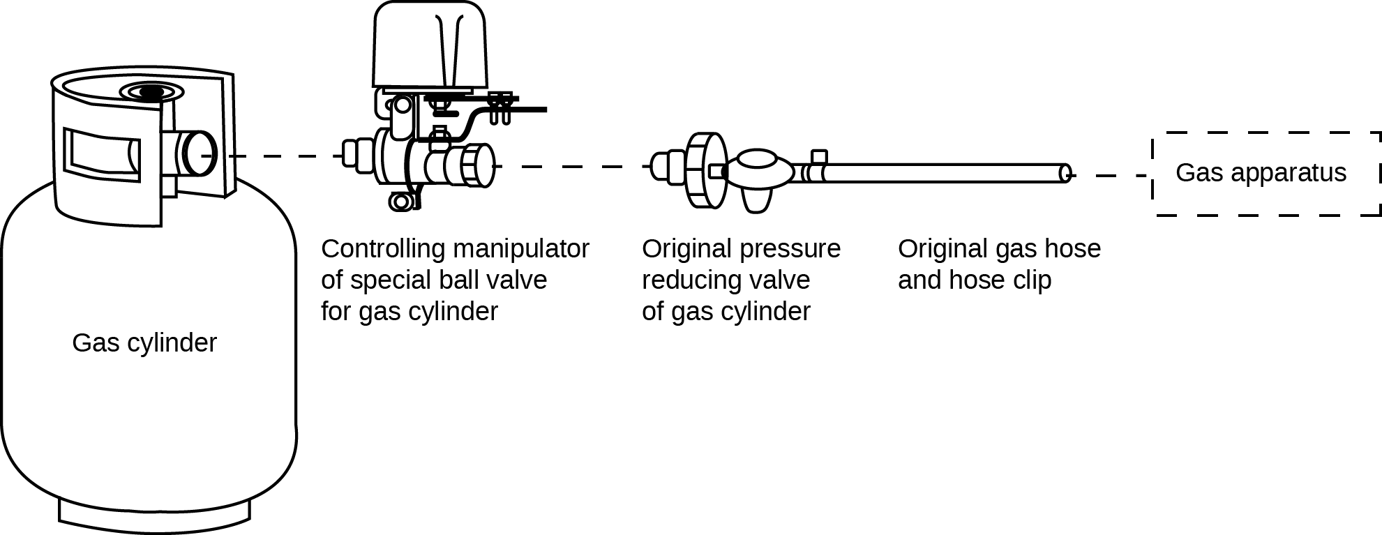
Its also possible to install the Flow Stop on a gas bottle as shown below.
Product Usage
The Flow Stop can be operated in three different ways.
- Remotely using Z-Wave wireless on/off commands. The device will appear in your controller as a simple on/off switch easy to operate. To protect the device from tampering or wrongdoing you can limit the remote operations using the configuration parameter #1.
- Local operation by simple pushing the red button. Any push of the button will result in a change of the status from open to close or vice versa.
- Mechanical overwrite allows opening or closing the valve even in case of a power failure. Disconnect the valve using the internal clutch by pulling the ring. Keep the ring pulled while moving the handle manually. Never move the handle without having the clutch disconnected. As best it will not work, as worst case it will destroy the device. Operating the valve manually only works without power supply. If the Flow Stop is powered and you operate the valve the motor will drive it into previous position immediately.
| Reset to factory default | press the button for at least 10 seconds. |
| Inclusion | 1. Connect the device as described.
2. Press the Red button three times in succession. |
| Exclusion | 1. Press the red button three times. |
| NIF | press the red inclusion button 3 times |
| Wakeup | XXXWakeupDescription |
| Protection | XXXProtection |
| FirmwareUpdate | XXXFirmwareUpdate |
| SetAssociation | XXXSetAssociation |
Association Groups:
| Group Number | Maximum Nodes | Description |
|---|---|---|
| 1 | 10 | Lifeline |
| 2 | 10 | Valve |
Technical Data
| Dimensions | 70x93x77 mm |
| Weight | 340 gr |
| Hardware Platform | ZM3102 |
| EAN | 0019962009501 |
| IP Class | IP 64 |
| Device Type | Central Controller |
| Generic Device Class | Binary Switch |
| Specific Device Class | Binary Switch |
| Z-Wave Version | 4.54.02 |
| Certification ID | ZC08-14030002 |
| Z-Wave Product Id | 0x0154.0x0003.0x0512 |
| Valve Pressure | 1.6 Mpa |
| Valve Sizes | 1/2 inc, 3/4 inc, 1 inc, 1.25 inc, 1.5 inc |
| Auto Close Time | 10 seconds |
| Auto Open Time | 10 seconds |
| Frequency | Europe - 868,4 Mhz |
| Maximum transmission power | 5 mW |