Popp
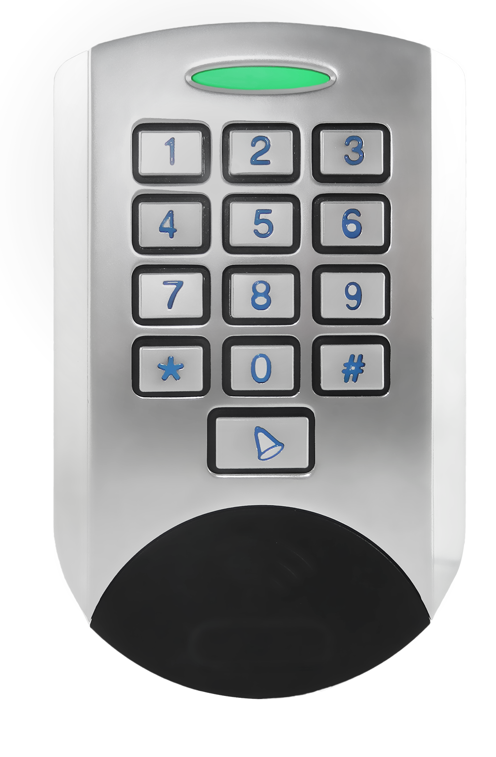
Universal Z-Wave Key Pad
SKU: POPE700045


Quickstart
This is a
 The device can run in two different modes determined by the way its included:
After finishing initial setup please set a Master Code (as user code #20) to protect your device. After Master Code (or user code #20) is set the management mode can only be reached by entering the Master Code, regardless if the device is open or closed. You need to reset the device in this case.
Important safety information
Please read this manual carefully. Failure to follow the recommendations in this manual may be dangerous or may violate the law. The manufacturer, importer, distributor and seller shall not be liable for any loss or damage resulting from failure to comply with the instructions in this manual or any other material. Use this equipment only for its intended purpose. Follow the disposal instructions. Do not dispose of electronic equipment or batteries in a fire or near open heat sources.Product Description
- Stand Alone Mode. In this case the keypad acts as the primary network controller and will include other devices such as e.g. a strike lock control or a door bell. No other central controller is needed. The management of user codes is done using the keypad itself.
- Network Mode. The keypad is included as additional device into an exiting network. In Z-Wave terms it will then act as inclusion (secondary) controller. It will send commands to a central controller and is managed by this controller. In this mode the device can still directly control door locks but it can also be used to trigger scenes in a central controller.
Installation
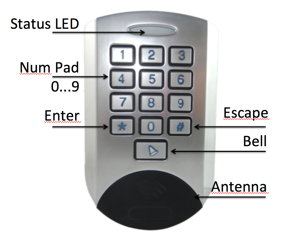
The image above shows the main functions an buttons of the device.
- When you open the device (remove the backside cover) the management mode is activated if master user code (20) is not present. Otherwise only entering master user code(20) will activate management mode.
- Entering the key code #20 will enter the management mode even when the tamper switch is closed.
 In management mode there is a preset user code 0-0-0-0 for test purposes (only active when enclosure opened and no other user codes present). This code is a valid user code resulting in a Door Open Command sent into Association Group 2.
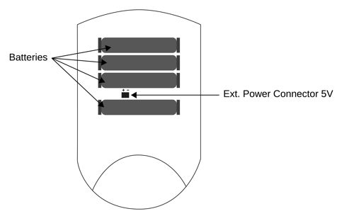
 The keypad is powered by 4 standard batteries. Two of them always run in parallel therefore the device will work if only two batteries are inserted. However the lifetime will be 50 % only. The device can be powered by a 5V DC external power supply. Between the batteries there is a small connector for the external power supply. It is safe to keep the batteries inserted for fall-back.
Product Usage
The keypad allows typing in up to 20 different key codes and pressing certain dedicated buttons. Key codes are numbered 1...20 must have minimum 4 and maximum 10 digits as number between 0 und 9. All key codes are equal except key code #20 that will also activate the management mode. Beside the 10 numerical keys the devices offers a ENTER key (*), an ESCAPE key (#) and a Bell key. Every key entry needs to be confirmed by "*". Sequences can be aborted using the "#" key.
The bell key will immeditately cause ringing a bell if there is a bell devices included in association group 3. They entry of the key code should be confirmed by "*". If no "*" is entered the entry will time out and use the key entered so far. This means its possible not to confirm by "*" and wait for the timeout of few seconds.
Stand Alone Mode
test of included stike lock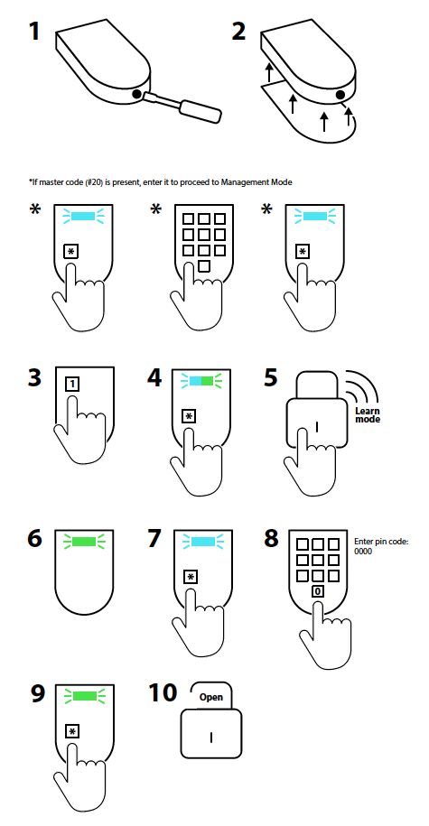 Test of included bell switch Test of included bell switch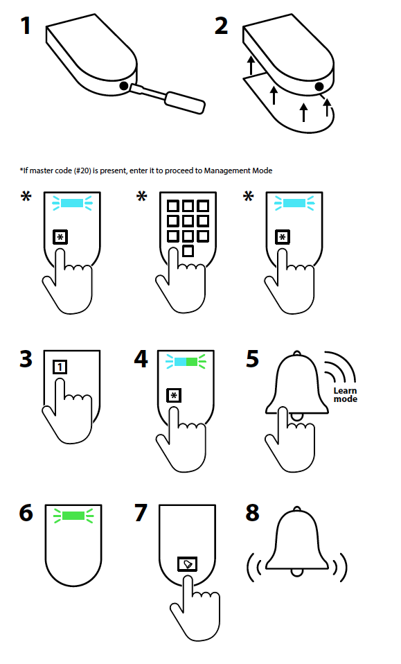 |
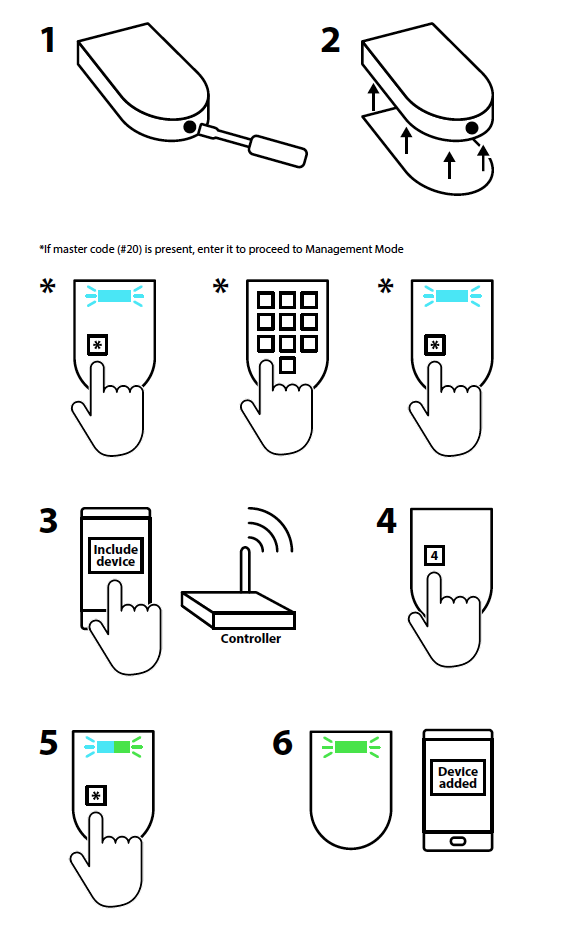
The purpose of the stand-alone mode is to use the keypad together with a door lock and a indicator device (Door bell, light switch ? to indicate bell ring). The keypad has two control groups (in Z-Wave language association group), one to control a door lock using key codes and one controlling the door bell using the bell key. So simplify the setup process the keypad will automatically place the first included door lock into the control group for door locks (#2) and the first included binary switch into control group for doorbell (#3). The two image sequences below show how to include a door lock (e.g. strike lock) and/or a a switch acting as door chime into a stand alone key pad. Hence to setup the keypad for simple door control, perform the following steps:
|
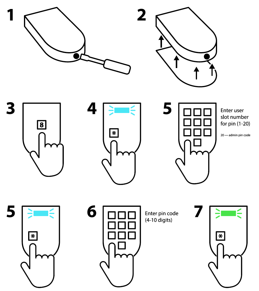 |
It is also possible to manage the keycodes to operate the door lock when being in the management mode. The image sequence shows how to do this.
|
Network Mode
The purpose of the network mode is to use the keypad as control device for the whole Smart Home.
This means that after including the keypad into the network of the central controller this very controller will receive event notifications for all actions performed on the keypad:
- Entering a valid key code (Scene ID 20 is issued). Its possible to issue the key code number as scene ID by setting the configuration parameter #5 accordingly
- Hitting the bell button once: Scene ID 21
- Hitting the bell button twice within one second: Scene ID 22
- Entering a invalid key code : Scene ID 23
Attention: If you use the keypad as device with Popp-Hub or any other Z-Way based controller you need ot install the app Keypad for
- managaging user codes
- accessing the usage history (keycodes entered, failed attempts)
Management
- In network mode the management of user codes can be done both locally on the keypad and using the central controllers Graphical User Interface. In case the central control offers a user interface for door lock management a history of valid and invalid key code entries can be accessed.
- While in network mode the keypad can also directly control door locks and bells using the association functions built in. Just include the door lock and the switch from your central controller and use the central controllers Z-Wave association management interface to place the lock in association group 2 and the bell switch in association group 3. Its also possible to use the key codes mentioned in the quick start to set and unset these associations.
Indications
- When the device is in standby no LED is on.
- Turning on management mode or activating the button for further button entry turns the blue LED on. Every recognized button push will turn off the blue background for a moment to confirm successful button press
- Depending on Configuation Parameter 6 the buzzer will sound to confirm any button press.
- The status LED indicates:
- Success: green blinks for one second
- Error: red blink for 3,5 seconds
- Learn Mode: blue/green are blinking constantly
- Next Menu: blue LED blinks for one second
- Waiting for user code: blue LED blinks fast
- Waiting for reset: blue LED blinks very fast
- Management Mode: green blinking slowly
- Inclusion/Exclusion: red/green LEDs are blinking constantly
Notifications
The device sends the following notifications to the central controller using Lifeline:
- Access Control (0x06): "Manual code exceeds limits (0x13)"; Sent, when pin code entered is more then 10
- Access Control (0x06): "Invalid User Code (0x14)";Sent, when entered pin code doesn?t exist
- Access Control (0x06): "Keypad Unlock (0x06)"; Sent, when entered pin code is correct and door is opened. This command also encapsulates the USER_CODE_REPORT with the pin entered
- Access Control (0x06): "All User Codes Deleted (0x0c)";Sent, when all pin codes arre removed by command from controller
- Access Control (0x06): "Single User Code deleted (0x0d)";Sent, when new pin code is removed by command from controller, or manually on the keypad
- Access Control (0x06): "New User Code added (0x0e)"; Sent, when new pin code is added by command from controller, or manually on the keypad
- Access Control (0x06): "New User Code not added (0x0f)"; Sent, when after attempt to add new pin code, using keypad
- Burglar Alarm (0x07): "Tamper Removed"; When keypad is unmounted and enclosure is opened
BASIC Command Handling
Basic Command Class is not supported and received Basic commands are ignored.
Known Problems
Association Group2 do not send DoorlockCC: Include the Popp Keypad second time again after door lock
| Reset to factory default | Open the device, hit button "5", then keep button "*" pressed for 10 seconds. The blue LED will start flashing the last 5 seconds of the waiting time. |
| Inclusion | 1. Open the housing.
2. Insert the batteries.
3. Press the buttons 4 and * in succession. |
| Exclusion | 1. Open the housing.
2. If a management code has been assigned, enter the code. 3. Press the buttons 4 and * in succession. |
| NIF | Hit 0 plus * (Star Key) in Management Mode |
| Wakeup | hit Ring Key |
| Protection | XXXProtection |
| FirmwareUpdate | hit * (Star Key) |
| SetAssociation | XXXSetAssociation |
Association Groups:
| Group Number | Maximum Nodes | Description |
|---|---|---|
| 1 | 10 | Lifeline |
| 2 | 10 | Door Lock Control |
| 3 | 10 | Ring Button Control |
Special Operations as Z-Wave Controller
As long as this device is not included into a Z-Wave network of a different controller it is able to manage its own Z-Wave network as primary controller. As a primary controller the device can include and exclude other devices in its own network, manage associations, and reorganize the network in case of problems. The following controller functions are supported:
Inclusion of other devices
Communication between two Z-Wave devices only works if both belong to the same wireless network. Joining a network is called inclusion and is initiated by a controller. The controller needs to be turned into the inclusion mode. Once in this inclusion mode the other device needs to confirm the inclusion - typically by pressing a button.
If current primary controller in your network is in special SIS mode this and any other secondary controller can also include and exclude devices.
To become primary a contoller have to be resetted and then include a device.
Turn into Management Mode, hit button 1 and confirm with * (Star Key)
Exclusion of other devices
The primary controller can exclude devices from the Z-Wave network. During exclusion the relationship between the device and the network of this controller is terminated. No communication between the device and other devices still in the network can happen after a successful exclusion. The controller needs to be turned into the exclusion mode. Once in this exclusion mode the other device needs to confirm the exclusion - typically by pressing a button.
Attention: Removing a device from the network means that it is turned back into factory default status. This process can also exclude devices from it's previous network.
Turn into Management Mode, hit button 2 and confirm with * (Star Key)
Shift of Primary Controller Role
The device can hand over its primary role to another controller and become secondary controller.
Turn into Management Mode, hit button 3 and confirm with * (Star Key). To update the network informsation from a primary controller please activate Learn mode.
This operation will replicate all network functions and the information about the nwetwork topology from this device to the new primary controller. If yoi want to update the network information in other controllers without handing of the primary function, just reinclude this other controller.
Configuration Parameters
Parameter 1: Door Lock Automatic Secure Timeout
After this time a CLOSE command is sent to the controlled door lock. On default no CLOSE command is sent assuming that the strike lock has its own timeout set Size: 1 Byte, Default Value: 3
| Setting | Description |
|---|---|
| 0 - 127 | Seconds |
Parameter 2: Ring Button Press Basic Command OFF Timeout
After this time the Door Bell will receive an OF command regardless of the actuall button is pressed or not Size: 1 Byte, Default Value: 3
| Setting | Description |
|---|---|
| 3 - 127 | Seconds |
Parameter 3: Ring Button ON Command
This value is sent into Association Group 3 when the door bell button is pressed. Size: 1 Byte, Default Value: 255
| Setting | Description |
|---|---|
| 0 - 99 | Basic Set Command Value |
| 255 | Basic Set Command Value |
Parameter 4: Ring Button OFF Command
This value is sent into Association Group 3 when the door bell button is released or the timeout has reached. Size: 1 Byte, Default Value: 0
| Setting | Description |
|---|---|
| 0 - 99 | Basic Set Command Value |
| 255 | Basic Set Command Value |
Parameter 5: Central Scene ID for User Codes
This parameter defines if different user codes shall cause individual or similar scene ID sent to the main controller. Size: 1 Byte, Default Value: 1
| Setting | Description |
|---|---|
| 0 | Constant Scene ID 20 for all User Codes |
| 1 | Individual User Codes 1 ... 20 |
Parameter 6: Buzzer Confirmation
Size: 1 Byte, Default Value: 1
| Setting | Description |
|---|---|
| 0 | Disabled |
| 1 | Enabled |
Technical Data
| Dimensions | 120x75x25 mm |
| Weight | 230 gr |
| Hardware Platform | ZM5101 |
| EAN | 4251295700045 |
| IP Class | IP 44 |
| Voltage | 5V DC |
| Battery Type | 4 * AAA |
| Device Type | Keypad |
| Generic Device Class | Portable Controller |
| Network Operation | Portable Controller |
| Firmware Version | 01.05 |
| Z-Wave Version | 6.51.10 |
| Certification ID | ZC10-17085733 |
| Z-Wave Product Id | 0115.0100.0103 |
| Frequency | Europe - 868,4 Mhz |
| Maximum transmission power | 5 mW |