Popp
Z-Wave Outdoor Weather Station
SKU: POPE700786


Quickstart
This is a
Important safety information
Please read this manual carefully. Failure to follow the recommendations in this manual may be dangerous or may violate the law. The manufacturer, importer, distributor and seller shall not be liable for any loss or damage resulting from failure to comply with the instructions in this manual or any other material. Use this equipment only for its intended purpose. Follow the disposal instructions. Do not dispose of electronic equipment or batteries in a fire or near open heat sources.What is Z-Wave?
Z-Wave is the international wireless protocol for communication in the Smart Home. This device is suited for use in the region mentioned in the Quickstart section.
Z-Wave ensures a reliable communication by reconfirming every message (two-way communication) and every mains powered node can act as a repeater for other nodes (meshed network) in case the receiver is not in direct wireless range of the transmitter.
This device and every other certified Z-Wave device can be used together with any other certified Z-Wave device regardless of brand and origin as long as both are suited for the same frequency range.
If a device supports secure communication it will communicate with other devices secure as long as this device provides the same or a higher level of security. Otherwise it will automatically turn into a lower level of security to maintain backward compatibility.
For more information about Z-Wave technology, devices, white papers etc. please refer to www.z-wave.info.
Product Description
The Z-Wave Outdoor Weatherstation measures the intensity of illumination from three directions, wind speed, the outside temperature and the rain status and transfers the values to a Z-Wave controller. The device is powered by 230 V mains power and will act as a z-Wave repeater if needed. The device can control other Z-Wave devices when certain user defined threshold values such as ‘temperature undershooding/overshooting‘, ‘Rain detected‘ or ‘light level‘ are met. This function will work without having a central controller involved.
Prepare for Installation / Reset
Please read the user manual before installing the product.
In order to include (add) a Z-Wave device to a network it must be in factory default state. Please make sure to reset the device into factory default. You can do this by performing an Exclusion operation as described below in the manual. Every Z-Wave controller is able to perform this operation however it is recommended to use the primary controller of the previous network to make sure the very device is excluded properly from this network.
Reset to factory default
This device also allows to be reset without any involvement of a Z-Wave controller. This procedure should only be used when the primary controller is inoperable.
Keep the magnet button pushed for 10 seconds.
Safety Warning for Mains Powered Devices
ATTENTION: only authorized technicians under consideration of the country-specific installation guidelines/norms may do works with mains power. Prior to the assembly of the product, the voltage network has to be switched off and ensured against re-switching.
Installation
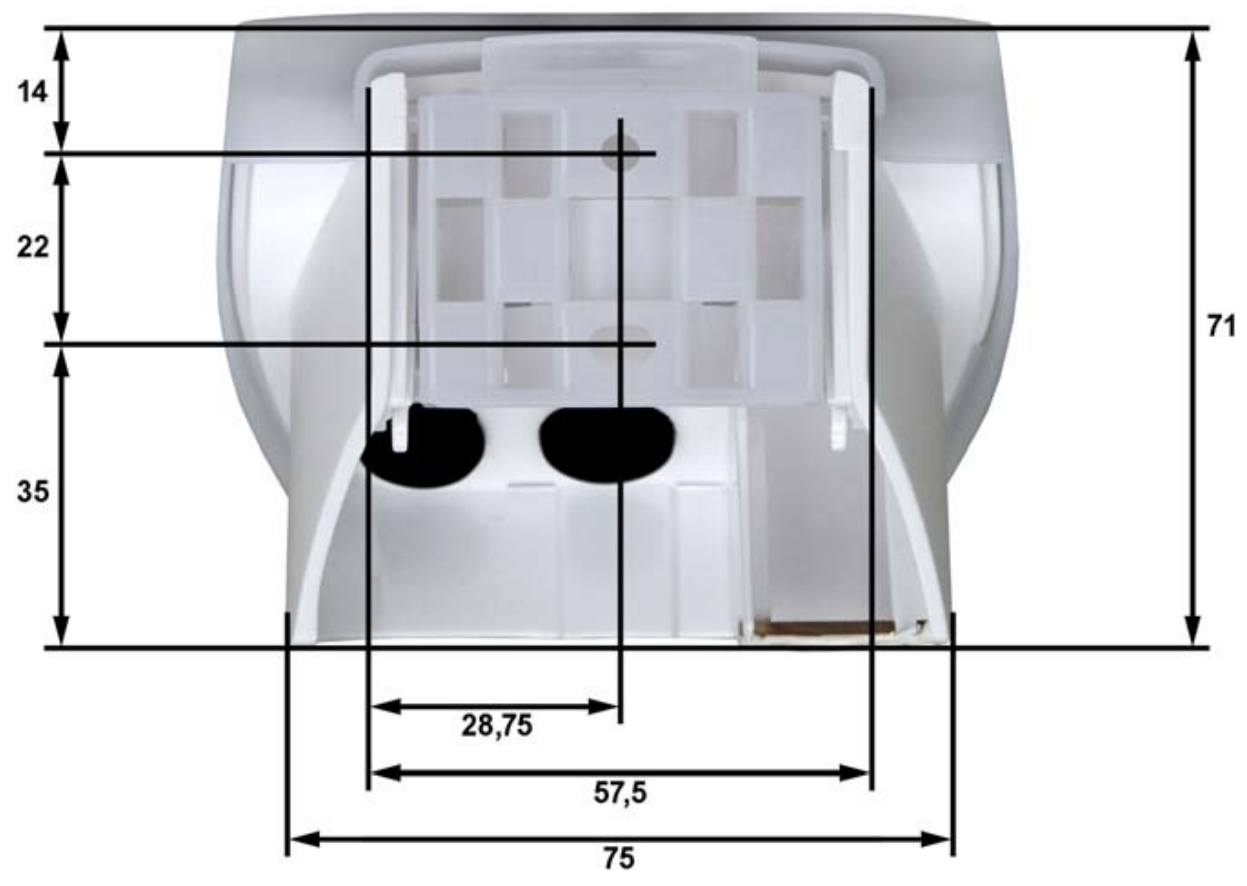
Select an assembly location at the building where sun and wind may be collected by the sensors unobstructedly. The sensor may not be shaded by the building or for example by trees. At least 60 cm of clearance must be left all round the device. This facilitates correct wind speed measurement without eddies. The distance concurrently prevents spray (raindrops hitting the device) or snow (snow penetration) from impairing the measurement. It also does not allow birds to bite it.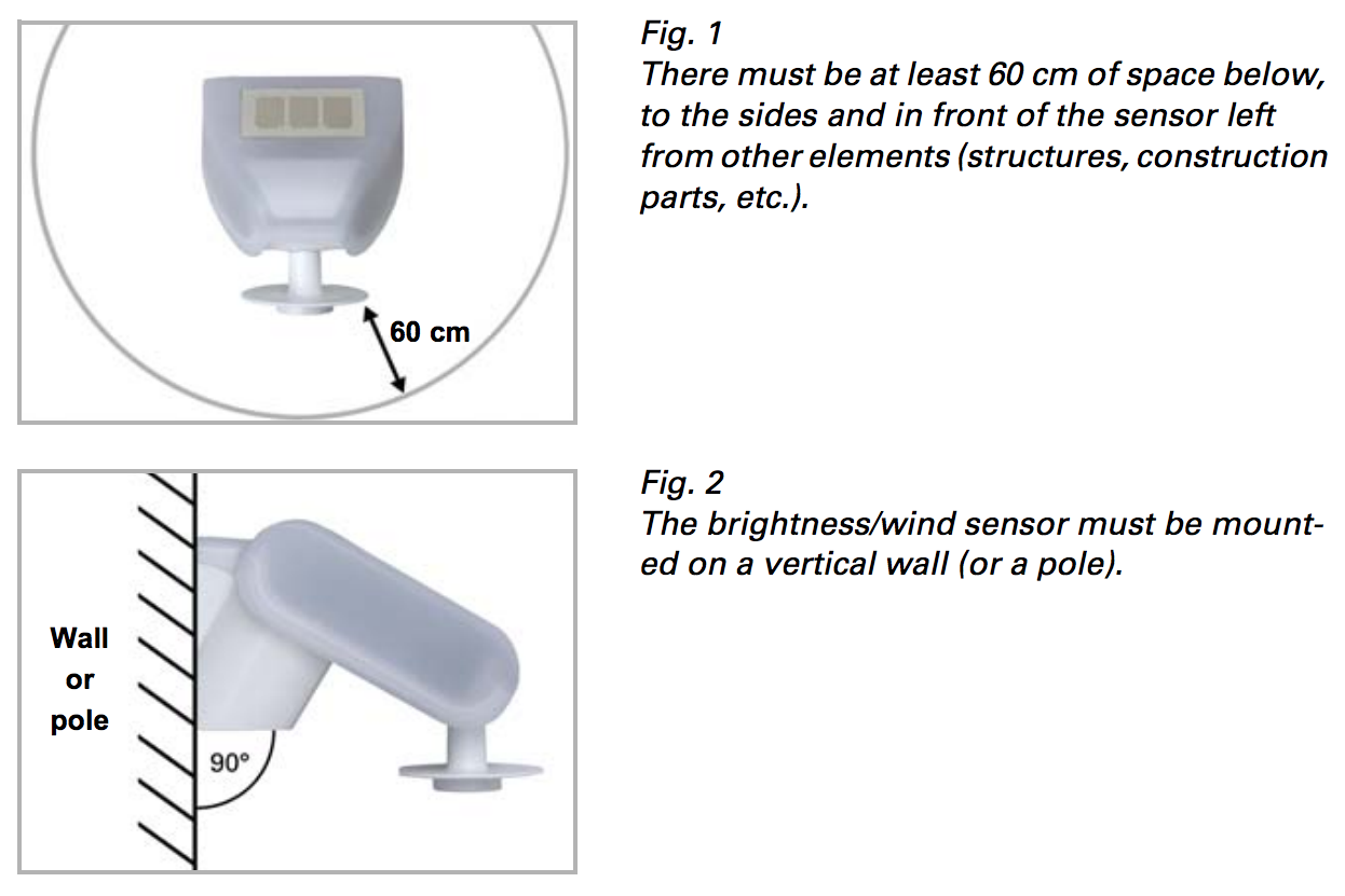
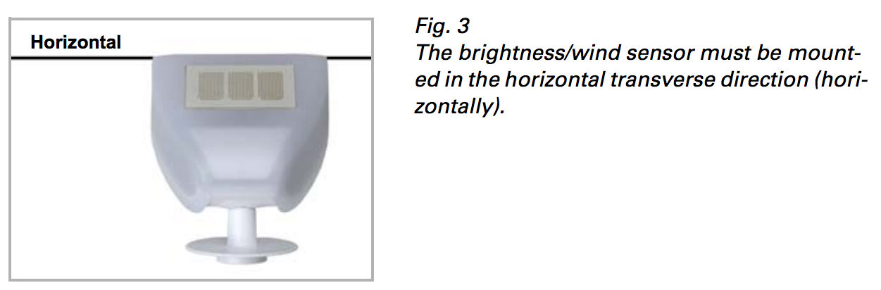
The sensor comes with a combination wall/pole mount. The mount comes adhered by adhesive strips to the rear side of the housing. Fasten the mount vertically onto the wall or pole. 
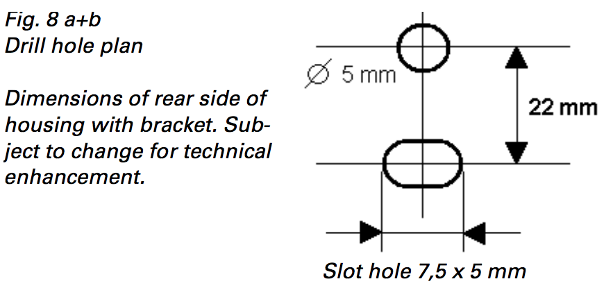
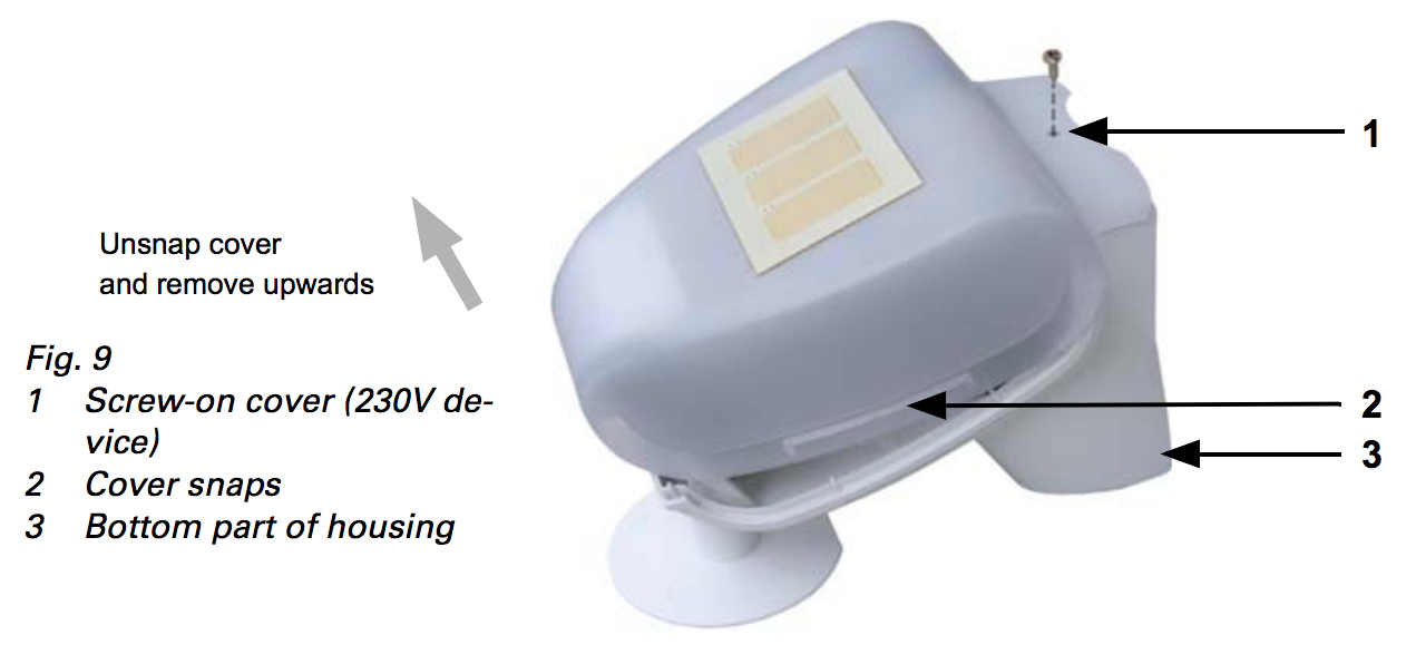
The sensor cover snaps in on the left and right along the bottom edge (see Fig. 9). Remove the cover. Proceed carefully, so as not to pull off the wire connecting the PCB in the bottom part with the cover.
Connect the two wires (N and L) of the 230 V power supply with the green terminals. Make sure the 230 V mains feed comes into the enclosure using the rubber gasket.
Some further notes on installation:
1. Do not open the device if water (rain) might ingress: even some drops might damage the electronic system.
2. Observe the correct connections. Incorrect connections may destroy the sensor or connected electronic devices.
3. The measured wind value and thus all other wind switching outputs may only be supplied 60 seconds after the supply voltage has been connected. After the auxiliary voltage has been applied, the device will enter an initialisation phase lasting a few seconds. During this phase no information can be received or sent wirelessly
Inclusion/Exclusion
On factory default the device does not belong to any Z-Wave network. The device needs to be added to an existing wireless network to communicate with the devices of this network. This process is called Inclusion.
Devices can also be removed from a network. This process is called Exclusion. Both processes are initiated by the primary controller of the Z-Wave network. This controller is turned into exclusion respective inclusion mode. Inclusion and Exclusion is then performed doing a special manual action right on the device.
Inclusion
Triple click of the magnet button. The magnet button is moving the supplied magnet towards the tip of the device and remove it fast. To force unsecure inclusion please keep the magnet button pushed for 2 seconds.Exclusion
Triple click of the magnet button. The magnet button is moving the supplied magnet towards the tip of the device and remove it fast.Product Usage
Once the device is installed its possible to call measured values from the device and let the device control other devices directly using association groups. The sensor of the device offer the following accuracy:
- Wind: Resolution 0.2 m/s between 0...35 m/s, ±22% of the measurement value when incident flow is from 45…315° ±15% of the measurement value when incident flow is from 90…270° (Frontal incident flow corresponds to 180°)
- Brightness: ±35% between 0...150.000 lux, Resulution: 1 lux at 0…120 lux 2 lux at 121…1.046 lux 63 lux at 1.047…52.363 lux 423 lux at 52.364…150.000 lux
- Temperature: -40…+80°C Resolution, 0.1°C Accuracy ±1°C at -10…+85°C ±1.5°C at -25…+150°C
The device will issue the following Z-Wave notifications:
- Heat overshoot
- Rain
- Wind overshoot
Quick trouble shooting
Here are a few hints for network installation if things dont work as expected.
- Make sure a device is in factory reset state before including. In doubt exclude before include.
- If inclusion still fails, check if both devices use the same frequency.
- Remove all dead devices from associations. Otherwise you will see severe delays.
- Never use sleeping battery devices without a central controller.
- Dont poll FLIRS devices.
- Make sure to have enough mains powered device to benefit from the meshing
Firmware-Update over the Air
This device is capable of receiving a new firmware 'over the air'. The update function needs to be supported by the central controller. Once the controller starts the update process, perform the following action to confirm the firmware update: Keep the magnet button pushed for 5 seconds.
Association - one device controls an other device
Z-Wave devices control other Z-Wave devices. The relationship between one device controlling another device is called association. In order to control a different device, the controlling device needs to maintain a list of devices that will receive controlling commands. These lists are called association groups and they are always related to certain events (e.g. button pressed, sensor triggers, ...). In case the event happens all devices stored in the respective association group will receive the same wireless command wireless command, typically a 'Basic Set' Command.
Association Groups:
| Group Number | Maximum Nodes | Description |
|---|---|---|
| 1 | 10 | Lifeline |
| 2 | 10 | Rain detected |
| 3 | 10 | Temperature overshoot |
| 4 | 10 | Temperature undershoot |
| 5 | 10 | Velocity too high |
| 6 | 10 | Light level exceeded |
Configuration Parameters
Z-Wave products are supposed to work out of the box after inclusion, however certain configuration can adapt the function better to user needs or unlock further enhanced features.
IMPORTANT: Controllers may only allow configuring signed values. In order to set values in the range 128 ... 255 the value sent in the application shall be the desired value minus 256. For example: To set a parameter to 200 it may be needed to set a value of 200 minus 256 = minus 56. In case of a two byte value the same logic applies: Values greater than 32768 may needed to be given as negative values too.
Parameter 1: BASIC Command on Rain Start detected
This BASIC command value is sent into Association Group 2 when start of rain is detected. Size: 1 Byte, Default Value: 255
| Setting | Description |
|---|---|
| 0 - 99 | Command Value |
| -1 | Command Value |
| -2 | Do not send. |
Parameter 2: BASIC Command on Rain Start detected
This BASIC command value is sent into Association Group 2 when stop of rain is detected. Size: 1 Byte, Default Value: 0
| Setting | Description |
|---|---|
| 0 - 99 | Command Value |
| -1 | Command Value |
| -2 | Do not send |
Parameter 3: Temperature Reporting Threshold
Whenever the temperature changes by more then the threshold value set in this configuration value a sensor report is sent to devices in Association Group 1. Size: 1 Byte, Default Value: 10
| Setting | Description |
|---|---|
| 1 - 255 | 0.1 C |
| 0 | Disabled |
Parameter 4: Upper Temperature Command Threshold
This value defines the upper threshold of the temperature value. In case the temperature exceeds this value a command defined in configuration parameter 5 is sent into Association Group 3. If the temperature drops below this threshold a BASIC commands defined in configuration parameter 6 is sent into Association Group 3. Size: 2 Byte, Default Value: 113
| Setting | Description |
|---|---|
| -1000 - +1000 | 0.1 C |
Parameter 5: BASIC Command on above Upper Temperature Threshold
This BASIC command value is sent into Association Group 3 when the temperature raises above upper temperature level. Size: 1 Byte, Default Value: 255
| Setting | Description |
|---|---|
| 0 - 99 | Command Value |
| -1 | Command Value |
| -2 | Do not send |
Parameter 6: BASIC Command on below Upper Temperature Threshold
This BASIC command value is sent into Association Group 3 when the temperature raises above upper temperature level. Size: 1 Byte, Default Value: 0
| Setting | Description |
|---|---|
| 0 - 99 | Command Value |
| -1 | Command Value |
| -2 | Do not send |
Parameter 7: Lower Temperature Command Threshold
This value defines the lower threshold of the temperature value. In case the temperature exceeds this value a command defined in configuration parameter 8 is sent into Association Group 4. If the temperature drops below this threshold a BASIC commands defined in configuration parameter 9 is sent into Association Group 4. Size: 2 Byte, Default Value: 200
| Setting | Description |
|---|---|
| -1000 - +1000 | 0.1 C |
Parameter 8: BASIC Command on below Lower Temperature Threshold
This BASIC command value is sent into Association Group 4 when the temperature raises above lower temperature level. Size: 1 Byte, Default Value: 255
| Setting | Description |
|---|---|
| 0 - 99 | Command Value |
| -1 | Command Value |
| -2 | Do not send |
Parameter 9: BASIC Command on above Lower Temperature Threshold
This BASIC command value is sent into Association Group 4 when the temperature raises above lower temperature level. Size: 1 Byte, Default Value: 0
| Setting | Description |
|---|---|
| 0 - 99 | Command Value |
| -1 | Command Value |
| -2 | Do not send |
Parameter 10: Wind Reporting Threshold
Whenever the wind level changes by more then the threshold value set in this configuration value a sensor report is sent to devices in Association Group 1. Size: 1 Byte, Default Value: 10
| Setting | Description |
|---|---|
| 0 | Disabled |
| 1 - 255 | 0.1 meter/sec |
Parameter 11: Wind Level Command Threshold
This value defines the upper threshold of the wind force. In case the wind exceeds this value a command defined in configuration parameter 12 is sent into Association Group 5. If the winds drops below this threshold a BASIC commands defined in configuration parameter 13 is sent into Association Group 5. Size: 2 Byte, Default Value: 14
| Setting | Description |
|---|---|
| 1 - 2000 | 0.1 meter/sec |
| 0 | Disabled |
Parameter 12: BASIC Command on above Velocity Threshold
This BASIC command value is sent into Association Group 5 when the velocity raises above threshold level. Size: 1 Byte, Default Value: 255
| Setting | Description |
|---|---|
| 0 - 99 | Command Value |
| -1 | No Command Sent |
| -2 | Do not send |
Parameter 13: BASIC Command on below Velocity Threshold
This BASIC command value is sent into Association Group 5 when the velocity raises above threshold level. Size: 1 Byte, Default Value: 0
| Setting | Description |
|---|---|
| 0 - 99 | Command Value |
| -1 | Command Value |
| -2 | Do not send |
Parameter 14: Light Level Reporting Threshold
Whenever the light level changes by more then the threshold value set in this configuration value a sensor report is sent to devices in Association Group 1. Size: 2 Byte, Default Value: 10
| Setting | Description |
|---|---|
| 0 | Disabled |
| 1 - 2000 | Lux |
Parameter 15: Light Level Command Threshold
This value defines the upper threshold of the light level. In case the light level exceeds this value a command defined in configuration parameter 16 is sent into Association Group 6. If the light level drops below this threshold a BASIC commands defined in configuration parameter 17 is sent into Association Group 6. Size: 2 Byte, Default Value: 300
| Setting | Description |
|---|---|
| 0 - 2000 | Lux |
Parameter 16: BASIC Command on above Light Threshold
This BASIC command value is sent into Association Group 6 when the light level falls below threshold level. Size: 1 Byte, Default Value: 255
| Setting | Description |
|---|---|
| 0 - 99 | Command Value |
| -1 | Command Value |
| -2 | Do not send |
Parameter 17: BASIC Command on below Velocity Threshold
This BASIC command value is sent into Association Group 6 when the light level falls below threshold level. Size: 1 Byte, Default Value: 0
| Setting | Description |
|---|---|
| 0 - 99 | Command Value |
| -1 | Command Value |
| -2 | Do not send |
Technical Data
| Dimensions | 96 × 77 × 118 mm mm |
| Weight | 240 gr |
| Hardware Platform | ZM5202 |
| IP Class | IP 44 |
| Voltage | 230 V |
| Load | 20 mA |
| Device Type | Notification Sensor |
| Generic Device Class | Multilevel Sensor |
| Specific Device Class | Routing Multilevel Sensor |
| Network Operation | Always On Slave |
| Firmware Version | 01.00 |
| Z-Wave Version | 06.01 |
| Z-Wave Product Id | 0115.0100.0700 |
| Frequency | Europe - 868,4 Mhz |
| Maximum transmission power | 5 mW |
Supported Command Classes
- Sensor Binary (s2 Unauth)
- Sensor Multilevel (s2 Unauth)
- Association Grp Info (s2 Unauth)
- Device Reset Locally (s2 Unauth)
- Zwaveplus Info (s2 Unauth)
- Multi Channel (s2 Unauth)
- Configuration (s2 Unauth)
- Alarm (s2 Unauth)
- Manufacturer Specific (s2 Unauth)
- Powerlevel (s2 Unauth)
- Firmware Update Md
- Association (s2 Unauth)
- Version (s2 Unauth)
- Multi Channel Association (s2 Unauth)
- Security S2
Controlled Command Classes
- Basic
- Multi Channel
Explanation of Z-Wave specific terms
- Controller — is a Z-Wave device with capabilities to manage the network. Controllers are typically Gateways,Remote Controls or battery operated wall controllers.
- Slave — is a Z-Wave device without capabilities to manage the network. Slaves can be sensors, actuators and even remote controls.
- Primary Controller — is the central organizer of the network. It must be a controller. There can be only one primary controller in a Z-Wave network.
- Inclusion — is the process of adding new Z-Wave devices into a network.
- Exclusion — is the process of removing Z-Wave devices from the network.
- Association — is a control relationship between a controlling device and a controlled device.
- Wakeup Notification — is a special wireless message issued by a Z-Wave device to announces that is able to communicate.
- Node Information Frame — is a special wireless message issued by a Z-Wave device to announce its capabilities and functions.