Popp
Door and Window Sensor with Tilt Detection
SKU: POPE700892


Quickstart
This is a
Important safety information
Please read this manual carefully. Failure to follow the recommendations in this manual may be dangerous or may violate the law. The manufacturer, importer, distributor and seller shall not be liable for any loss or damage resulting from failure to comply with the instructions in this manual or any other material. Use this equipment only for its intended purpose. Follow the disposal instructions. Do not dispose of electronic equipment or batteries in a fire or near open heat sources.Product Description
The POPP Door/Window Sensor is a sensor, which detects, if your window is opened, closed or tilted. The sensor is easily retrofittable. Furthermore, the POPP Door/Window Sensor can include other sensors by being connected with other binary sensors like NTC contacts, micro switches or flood sensor.
Thanks to its slim design the POPP Door/Windows can be installed unflashy on every window. The sensor just has to be installed on the window casement. Additionally, there has to be a slim magnet installed closely to the sensor at the window frame. By using a patented method the sensor can reliably detect the exact position of the window.
With the potential free input the Door/Window Sensor can also include other sensors in your Z-Wave system. For that the binary sensor is connected to the potential free input of the sensor. Besides sensors there can also be connected momentary switches, which controls scenes in your gateway.
Installation
The sensor can be mounted either on the moving part or on the fixed part of a door or a window. Mounting can be accomplished either using the tape by peeling off the protection foil or using two screws with the holes inside the battery compartment. If the tilt detection on a window (only normal windows, no roof windows) shall be used the sensor device must be placed on the moving part of the window and the magnet on the window frame. The sensor comes with two types of magnets:
- The standard magnet covered by plastic part, mountable beside the sensor. Make sure the two indicating lines on sensor enclosure and magnet are opposite to each other. The image on the right handside shows the position of magnet and sensor body.
- A slim naked magnet to be mounted behind the sensor in case the sensor body is placed on the side of a window.
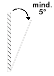
- To use the tilting function, the opening angle of the window must be at least 5°.
Product Usage
Once installed the sensor will report open and close status changes to a central Z-Wave controller using notification commands. Addtionally the sensor can directly control other device using the association group 2. Using configuration commands the source of open and close events can choosen between the internal magnet detector or external dry contact connected via the screw terminal. The device is protected by a tamper switch.
Tilt detection
The tilt detection allows reporting the way a window is opened. This is accomplished using the command class binary sensor - tilt type. In case the window is closed or opened without tilting the tilt sensor will report Off. In case the window is tilted a On is reported. The angle of inclination of the window must be at least 5°.
As of V1.02, the tilt sensitivity can be adjusted via Parmater 15. Note that the value 100 has a high sensitivity and the value 1 a very low sensitivity. The default value is 50.
Screw Terminal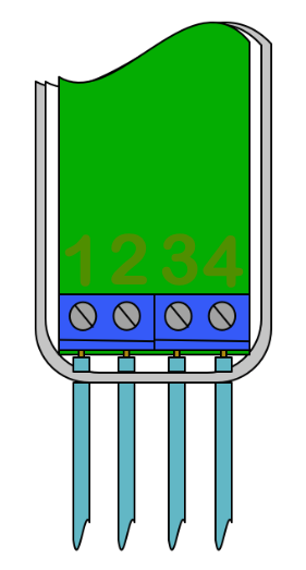
The product must support interconnection of external sensors as well as actuators and dry-contacts. Product allows interconnection with external sensors/actuators via 4-pin screw terminals with the following pinout:
- #1: VCC (direct battery supply)
- #2: Analogue Input (ADC - not used at the moment)
- #3: Digital Input
- #4: Ground
Link testing
When activated by configuration parameter #4 the device can perform a link test with device No.1. Double clicking the tamper will start the process. As a result the red LED will blink one time in case of success and three times in case of failure.
Scene Controller
When activated by configuration parameter #13 the device can perform as a scene controller. The external dry contact will then act as a scene controller with a total of 7 scenes that can be activated:
- 1 - Contact Pressed 1 time
- 2 - Contact Pressed 2 time
- 3 - Contact Pressed 3 time
- 4 - Contact Pressed 4 time
- 5 - Contact Pressed 5 time
- 6 - Contact held down
- 7 - Contact released
- Window Opened(0x06 - 0x16)
- Window Closed(0x06 - 0x17)
- Tamper Removed(0x07 - 0x03)
The device sends the following sensor binary reports to the controller:
- Tilt(0x0B)
| Reset to factory default | Once Cover is removed and tamper switch is tripped, push the tamper for 5 seconds until red LED blinks. Then release tamper and push it again for 5 seconds until LED blinks. |
| Inclusion | 1. Open the housing. 2. Remove the battery protection. 3. Press the tamper on the side of the appliance three times quickly. |
| Exclusion | 1. Open the housing. 2. Press the tamper on the side of the appliance three times quickly. |
| NIF | XXXNIF |
| Wakeup | XXXWakeupDescription |
| Protection | XXXProtection |
| FirmwareUpdate | Wake Up the device by removing the cover. The hit the tamper switch once. |
| SetAssociation | XXXSetAssociation |
Association Groups:
| Group Number | Maximum Nodes | Description |
|---|---|---|
| 1 | 5 | Lifeline |
| 2 | 5 | Control devices when magnet or external dry contacts trips |
| 3 | 5 | sends our alarm message when magnet controlled or external dry sensor trips. |
| 4 | 5 | sends alarm messages when tamper is tripped |
Configuration Parameters
Parameter 1: Sensor Operation Mode
This parameter defines if the internal magnet sensor or the external terminal input is detected and used to issue alarm notification. There is always one input active only. The other sensor input the deactivated. Size: 1 Byte, Default Value: 0
| Setting | Description |
|---|---|
| 0 | Internal Magnet Sensor Used |
| 1 | External Terminal Inputs Used |
Parameter 2: Sensor State Polarity
This parameter defines the polarity of the magnet sensor. Size: 1 Byte, Default Value: 0
| Setting | Description |
|---|---|
| 0 | Closed when Magnet in proximity |
| 1 | Opened when Magnet in proximity |
Parameter 3: Visual LED Indications
This parameter defines when the red LED will indicate events. Disabling all indications may extend battery life. Size: 1 Byte, Default Value: 7 (values 1 + 2 + 4 summarized)
| Setting | Description |
|---|---|
| 0 | No Indications |
| 1 | Open/Close Status Change |
| 2 | Wake Up |
| 4 | Device Tampering |
Parameter 4: Range Test after double click
Allows to enable the activation of a Z-Wave range test with double clicking the tamper switch. Size: 1 Byte, Default Value: 0
| Setting | Description |
|---|---|
| 0 | Disabled |
| 1 | Enabled |
Parameter 5: 2nd Association Group Trigger
This parameter defines the status of the magnet switch that causes sending a BASIC command to all devices of Association Group 2. Size: 1 Byte, Default Value: 0
| Setting | Description |
|---|---|
| 0 | Switch after Open and Close |
| 1 | Switch after Open |
| 2 | Switch after Close |
Parameter 6: Command Sent to Devices of Association Group 2
This parameter defines which commands is sent to 2nd Association Group Size: 1 Byte, Default Value: 2
| Setting | Description |
|---|---|
| 0 | On |
| 1 | Off |
| 2 | On and Off |
Parameter 7: BASIC command value sent to 2nd Association Group on On event
This is the BASIC command value sent in case of On event. Size: 1 Byte, Default Value: 255
| Setting | Description |
|---|---|
| 0 - 99 | Value |
| 255 | Value |
Parameter 8: BASIC command value sent to 2nd Association Group on Off event
This is the BASIC command value sent in case of Off event. Size: 1 Byte, Default Value: 0
| Setting | Description |
|---|---|
| 0 - 99 | Value |
| 255 | Value |
Parameter 9: Time Delay of Off command frame
Off command is sent after a delay defined in this parameter. Size: 2 Byte, Default Value: 0
| Setting | Description |
|---|---|
| 0 - 32400 | seconds |
Parameter 10: Time Delay of Off command frame
Off command is sent after a delay defined in this parameter. Size: 2 Byte, Default Value: 0
| Setting | Description |
|---|---|
| 0 - 32400 | seconds |
Parameter 11: Delay of Tamper Alarm Cancellation
Time a tamper alarm is delayed. Size: 2 Byte, Default Value: 0
| Setting | Description |
|---|---|
| 0 - 32400 | seconds |
Parameter 12: Reporting Tamper Alarm Cancellation
This parameter defines if the alarm cancellation event is reported. Size: 1 Byte, Default Value: 1
| Setting | Description |
|---|---|
| 0 | Do not send Report |
| 1 | Send Report |
Parameter 13: Central Scene Event Functionality
This parameter enables/disables the central scene function. Size: 1 Byte, Default Value: 0
| Setting | Description |
|---|---|
| 0 | Disabled |
| 1 | Enabled |
Parameter 14: Tilt Sensor Functionality
This parameter enables/disables the tilt function. Size: 1 Byte, Default Value: 1
| Setting | Description |
|---|---|
| 0 | Disabled |
| 1 | Enabled |
Parameter 15: Tilt sensitivity from V1.02 and higher
You can use this parameter to adjust the tilt sensitivity if the tilt is too low or too high. Size: 1 Byte, Default Value: 50
| Setting | Description |
|---|---|
| 1 - 100 | Tilt sensitivity |
Technical Data
| Dimensions | 28x95x35 mm |
| Hardware Platform | ZM5101 |
| EAN | 4251295700892 |
| IP Class | IP 20 |
| Battery Type | 1 * 1/2 AA |
| Device Type | Notification Sensor |
| Generic Device Class | Sensor Notification |
| Specific Device Class | Routing Sensor Notification |
| Network Operation | Reporting Sleeping Slave |
| Firmware Version | 01.00 |
| Z-Wave Version | 06.02 |
| Z-Wave Product Id | 0154.0004.0007 |
| Frequency | Europe - 868,4 Mhz |
| Maximum transmission power | 5 mW |