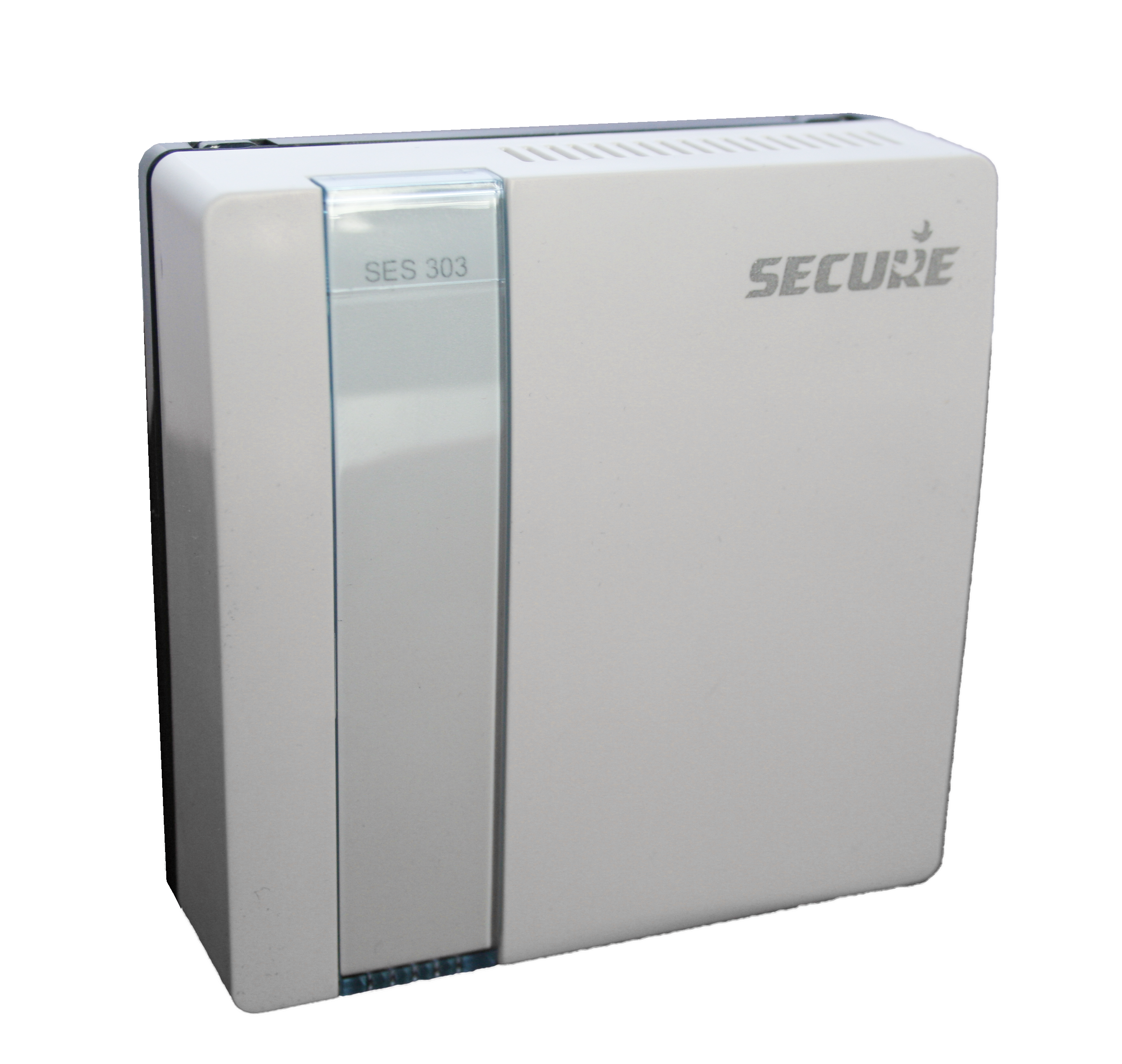
Secure
SSR 303 (Single Channel On/Off Power switch)
SKU: SECESSR303-5

Quickstart
This is a
STEP 2: Put the 3rd party controller into inclusion mode.
STEP 3: Press and hold the network button on the SSR 303 until the ON LEDs start flashing. The SSR 303 has been added onto the network when the OFF LED goes solid red.
NOTE: If the ON LED does not flash then the add process has been unsuccessful.
Important safety information
Please read this manual carefully. Failure to follow the recommendations in this manual may be dangerous or may violate the law. The manufacturer, importer, distributor and seller shall not be liable for any loss or damage resulting from failure to comply with the instructions in this manual or any other material. Use this equipment only for its intended purpose. Follow the disposal instructions. Do not dispose of electronic equipment or batteries in a fire or near open heat sources.Product Description
The SSR 303 is a single channel relay/switch, it forms part of central heating control system, it can be operated by any third party controllers/Thermostat using Binary Switch CC commands.
SSR 303 will act as a repeater once added into the Z- Wave network, providing an alternative communication route for units which otherwise would not be within communication distance of each other.
SSR 303 has a fail-safe mode where by the relay is turned OFF if another ‘Thermostat Mode SET‘ command has not been received within 60 minutes.
Installation
The SSR303 receiver should be located as near as is practical to the device to be controlled, as well as a convenient mains electricity supply. To remove the wall plate from the SSR303, undo the two retaining screws located on the underside, the wall plate should now be easily removed. Once the wall plate has been removed from the packaging please ensure the SSR303 is re-sealed to prevent damage from dust, debris etc.
The wall plate should be fitted with the retaining screws located at the bottom and in a position which allows a total clearance of at least 50mm around the SSR303 receiver.
Direct Wall Mounting
Offer the plate to the wall in the position where the SSR303 is to be mounted and mark the fixing positions through the slots in the wall plate. Drill and plug the wall, then secure the plate into position. The slots in the wall plate will compensate for any misalignment of the fixings.
Wall Box Mounting
The wall plate may be fitted directly on to a single gang flush wiring box complying with BS4662, using two M3.5 screws. The receiver is suitable for mounting on a flat surface only; it is not suitable for mounting on an unearthed metal surface.
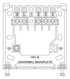
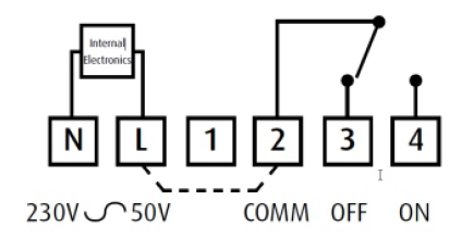
Electrical Connections
All necessary electrical connections should now be made. Flush wiring can enter from the rear through the aperture in the backplate. The mains supply terminals are intended to be connected to the supply by means of fixed wiring. The receiver is mains powered and requires a 3 Amp fused spur. The recommended cable size is 1.Omm2. The receiver is double insulated and does not require an earth connection, an earth connection block is provided on the backplate for terminating any cable earth conductors. Earth continuity must be maintained and all bare earth conductors must be sleeved. Ensure that no conductors are left protruding outside the central space enclosed by the backplate.
Product Usage
The SSR303 receiver unit receives the Z-Wave radio signals from the 3rd party Z-wave controllers. In the unlikely event of a communication failure it is possible to override the system and switch On and Off using the On/Off buttons on the SSR303 receiver as a local override.
If the override is used to override the system when it is functioning correctly then the override will be cancelled by the next switching operation and normal operation will be resumed. In any case, with no further intervention, normal operation will be restored within one hour of the override being operated.
Receiver status LED
This unit has three buttons and three LEDs - ON, OFF and Network (from top to bottom) that are used as follows:
Solid OFF LED Flashing Network LED - Unit is currently removed from the network
Flashing ON LED (Green) 3s only Solid OFF LED - Unit has been successfully added on the network
Solid OFF LED - Unit is reflecting the status OFF the relay unit. The output is OFF.
- Or, unit has finished the addition process.
- Or, unit has been added and has just been powered up on the mains
Solid ON LED - Unit is reflecting the status of the relay output. The output is ON.
Solid OFF LED Solid Network LED - Unit is in failsafe mode and the relay output is OFF.
Solid ON LED Solid Network LED - Unit is in Failsafe mode and the relay output has been turned ON via the ON button
- Or, Unit is currently removed from the network and ON by button operation.
| Reset to factory default | XXXResetDescription |
| Inclusion | Press and hold the network button on the SSR 303 until the ON LEDs start flashing. |
| Exclusion | Press and hold the network button on the SSR 303. |
| NIF | Press an hold the network button for 1 seconds |
| Wakeup | XXXWakeupDescription |
| Protection | XXXProtection |
| FirmwareUpdate | XXXFirmwareUpdate |
| SetAssociation | XXXSetAssociation |
Association Groups:
| Group Number | Maximum Nodes | Description |
|---|---|---|
| 1 | 4 | Z-Wave Plus Lifeline group, SSR 303 will send unsolicited SWITCH BINARY REPORT to lifeline group. |
Technical Data
| Dimensions | 85 x 32 x85 mm |
| Weight | 138 gr |
| Hardware Platform | ZM5202 |
| EAN | 5015914250095 |
| IP Class | IP 30 |
| Voltage | 230 V |
| Load | 3 A |
| Device Type | On/Off Power Switch |
| Network Operation | Always On Slave |
| Z-Wave Version | 6.51.06 |
| Certification ID | ZC10-16075134 |
| Z-Wave Product Id | 0x0059.0x0003.0x0005 |
| Neutral Wire Required | ok |
| Color | White |
| IP (Ingress Protection) Rated | ok |
| Electric Load Type | Inductive |
| Frequency | Europe - 868,4 Mhz |
| Maximum transmission power | 5 mW |