Secure
RF Coutdown Timer
SKU: SEC_SIR321
Quickstart
This is a
Press and hold the pairing button on the unit until the RF LED starts flashing at a fast rate. Then release the button. On successful inclusion the RF LED will stop flashing.
Important safety information
Please read this manual carefully. Failure to follow the recommendations in this manual may be dangerous or may violate the law. The manufacturer, importer, distributor and seller shall not be liable for any loss or damage resulting from failure to comply with the instructions in this manual or any other material. Use this equipment only for its intended purpose. Follow the disposal instructions. Do not dispose of electronic equipment or batteries in a fire or near open heat sources.What is Z-Wave?
Z-Wave is the international wireless protocol for communication in the Smart Home. This device is suited for use in the region mentioned in the Quickstart section.
Z-Wave ensures a reliable communication by reconfirming every message (two-way communication) and every mains powered node can act as a repeater for other nodes (meshed network) in case the receiver is not in direct wireless range of the transmitter.
This device and every other certified Z-Wave device can be used together with any other certified Z-Wave device regardless of brand and origin as long as both are suited for the same frequency range.
If a device supports secure communication it will communicate with other devices secure as long as this device provides the same or a higher level of security. Otherwise it will automatically turn into a lower level of security to maintain backward compatibility.
For more information about Z-Wave technology, devices, white papers etc. please refer to www.z-wave.info.
Product Description
Secure Intelligent Relay is having One relay, and support of duration base schedule, measuring of temperature and delta and interval temperature reporting etc
Prepare for Installation / Reset
Please read the user manual before installing the product.
In order to include (add) a Z-Wave device to a network it must be in factory default state. Please make sure to reset the device into factory default. You can do this by performing an Exclusion operation as described below in the manual. Every Z-Wave controller is able to perform this operation however it is recommended to use the primary controller of the previous network to make sure the very device is excluded properly from this network.
Safety Warning for Mains Powered Devices
ATTENTION: only authorized technicians under consideration of the country-specific installation guidelines/norms may do works with mains power. Prior to the assembly of the product, the voltage network has to be switched off and ensured against re-switching.
Installation
A means of disconnection from the supply, having at least 3mm contact separation in both poles, must be incorporated in the fixed wiring. We recommend a separate fused circuit from the consumer unit (24-hour supply) protected by a 15A HRC fuse or, preferably a 16A MCB. In some cases immersion heater failure can damage the SIR. Installation of a 100mA RCD will provide additional protection for the unit. If the SIR is to be connected to a ring main then the spur feeding the controller should be protected in the same way. The SIR is NOT suitable for mounting on an unearthed metal surface.+
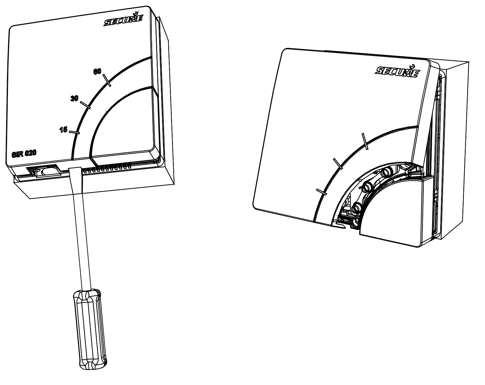
Take the SIR out of its packaging and then remove the front cover gently, using a slotted screwdriver in the notch, as shown in the picture below:
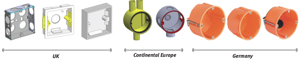
SIR is suitable for mounting directly on to any surface mounted single-gang moulded box having a minimum depth of 25mm for UK, or 35mm for Continental Europe. Cable entry can be made through the most convenient cut-out.
For flush wall mounting - SIR can be mounted directly to any standard flush mounting single-gang wiring box with a depth of 25mm for UK (BS 4662), or 35mm for Continental Europe (DIN 49073).
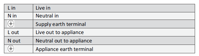
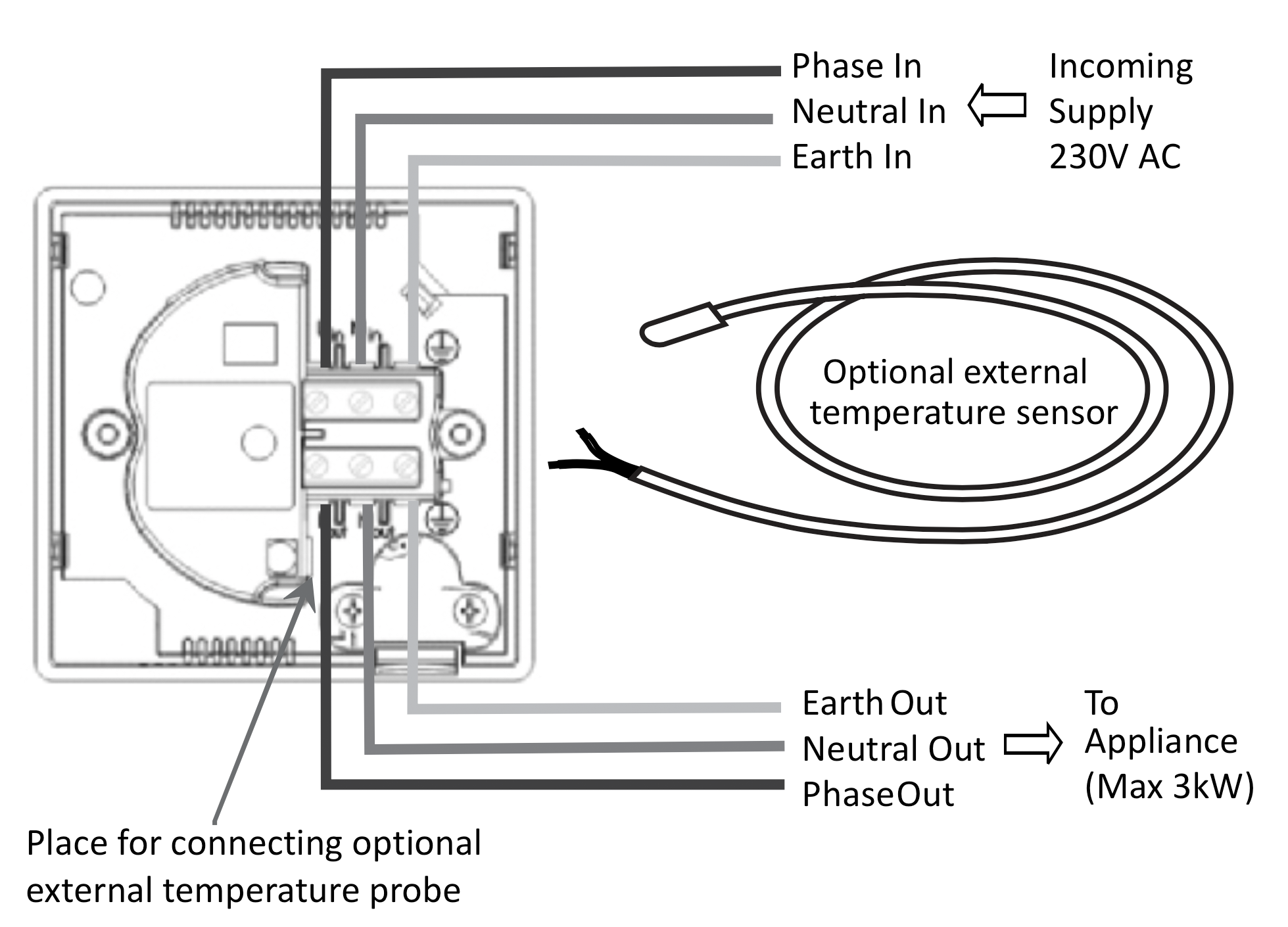
3. Making connections
Use twin-and-earth cable with a maximum conductor size of 2.5mm2 single conductor for the incoming supply to the SIR. Use a suitably rated three-core flexible cable to connect the SIR to the appliance to be switched. For appliances rated up to 2kW use minimum 1.0mm2 flexible conductors. For appliances rated up to 3kW use minimum 1.5mm2 flexible conductors. Heat resistant flexible cable must be used if connecting the SIR to an immersion heater.
Carefully offer the SIR to the moulded/metal box and secure using two screws. Take care not to damage the insulation or trap the conductors when fitting to flush wall box.
5.Z-Wave® commissioning notes
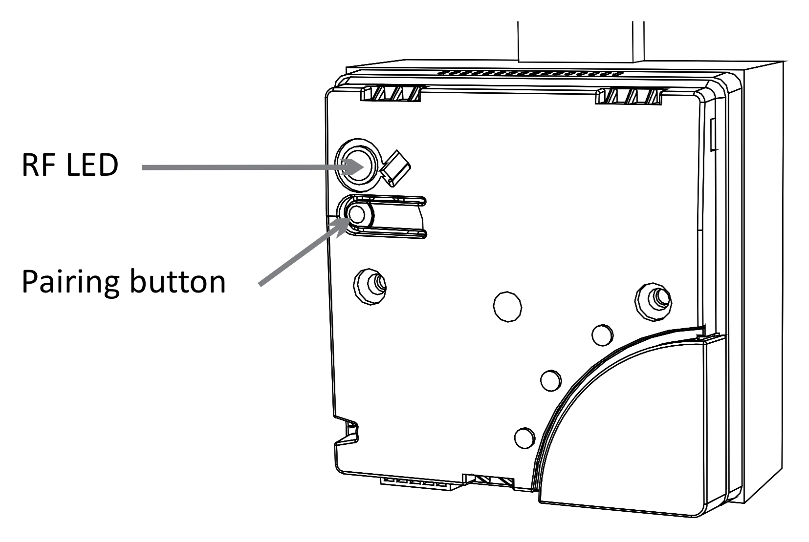
Unit not signed on to network: RF LED slow flashing
RF inclusion/exclusion process: RF LED fast flashing
RF link lost to the controller: RF LED glow solid
RF network is OK: RF LED off
After fitting the mounting screws, fix the front cover back on. Offer the front cover on to the unit and make sure that it clicks securely in place.
Inclusion/Exclusion
On factory default the device does not belong to any Z-Wave network. The device needs to be added to an existing wireless network to communicate with the devices of this network. This process is called Inclusion.
Devices can also be removed from a network. This process is called Exclusion. Both processes are initiated by the primary controller of the Z-Wave network. This controller is turned into exclusion respective inclusion mode. Inclusion and Exclusion is then performed doing a special manual action right on the device.
Inclusion
Press and hold the pairing button on the unit until the RF LED starts flashing at a fast rate. Then release the button. On successful inclusion the RF LED will stop flashing.Exclusion
Press and hold the pairing button on the unit until the RF LED starts flashing at a fast rate. Then release the button. On successful inclusion the RF LED will stop flashing.Node Information Frame
The Node Information Frame (NIF) is the business card of a Z-Wave device. It contains information about the device type and the technical capabilities. The inclusion and exclusion of the device is confirmed by sending out a Node Information Frame. Beside this it may be needed for certain network operations to send out a Node Information Frame. To issue a NIF execute the following action: Press the Z-Wave Button
Quick trouble shooting
Here are a few hints for network installation if things dont work as expected.
- Make sure a device is in factory reset state before including. In doubt exclude before include.
- If inclusion still fails, check if both devices use the same frequency.
- Remove all dead devices from associations. Otherwise you will see severe delays.
- Never use sleeping battery devices without a central controller.
- Dont poll FLIRS devices.
- Make sure to have enough mains powered device to benefit from the meshing
Association - one device controls an other device
Z-Wave devices control other Z-Wave devices. The relationship between one device controlling another device is called association. In order to control a different device, the controlling device needs to maintain a list of devices that will receive controlling commands. These lists are called association groups and they are always related to certain events (e.g. button pressed, sensor triggers, ...). In case the event happens all devices stored in the respective association group will receive the same wireless command wireless command, typically a 'Basic Set' Command.
Association Groups:
| Group Number | Maximum Nodes | Description |
|---|---|---|
| 1 | 4 | Nodes to receive Schedule report |
| 2 | 4 | Nodes to receive multilevel sensor report Note: Group-2 is available only when external temp sensor is connected. |
Configuration Parameters
Z-Wave products are supposed to work out of the box after inclusion, however certain configuration can adapt the function better to user needs or unlock further enhanced features.
IMPORTANT: Controllers may only allow configuring signed values. In order to set values in the range 128 ... 255 the value sent in the application shall be the desired value minus 256. For example: To set a parameter to 200 it may be needed to set a value of 200 minus 256 = minus 56. In case of a two byte value the same logic applies: Values greater than 32768 may needed to be given as negative values too.
Parameter 1: Enable Fail safe timer
Size: 1 Byte, Default Value: 0
| Setting | Description |
|---|---|
| 0 - 255 | Value |
Parameter 2: Temperature Scale
Size: 1 Byte, Default Value: 0
| Setting | Description |
|---|---|
| 0 - 127 | °C |
| 128 - 255 | °F |
Parameter 3: Temperature reporting intervals
Size: 2 Byte, Default Value: 0
| Setting | Description |
|---|---|
| 1 - 65534 | Seconds |
Parameter 4: Delta configuration temperature reporting
Size: 2 Byte, Default Value: 0
| Setting | Description |
|---|---|
| 1 - 100 | °C in 0,1°C |
| 1 - 500 | °F in 0,1°F |
Parameter 5: Temperature Cutoff
Size: 2 Byte, Default Value: 0
| Setting | Description |
|---|---|
| 1 - 1000 | °C in 0,1°C |
| 320 - 2120 | °F in 0,1°F |
Technical Data
| Dimensions | 85x85x44 mm |
| Weight | 123 gr |
| Hardware Platform | ZM3102 |
| EAN | 5015914083563 |
| IP Class | IP IP 20 |
| Voltage | 230 V |
| Load | 3000 W |
| Device Type | Central Controller |
| Generic Device Class | Binary Switch |
| Specific Device Class | Specific Device Class not used |
| Z-Wave Version | 4.53 |
| Certification ID | ZC08-14040014 |
| Z-Wave Product Id | 0x0059.0x0010.0x0002 |
| Frequency | Europe - 868,4 Mhz |
| Maximum transmission power | 5 mW |
Supported Command Classes
- Association
- Basic
- Configuration
- Manufacturer Specific
- Sensor Multilevel
- Schedule
- Switch Binary
- Version
Controlled Command Classes
- Basic
- Switch Binary
Explanation of Z-Wave specific terms
- Controller — is a Z-Wave device with capabilities to manage the network. Controllers are typically Gateways,Remote Controls or battery operated wall controllers.
- Slave — is a Z-Wave device without capabilities to manage the network. Slaves can be sensors, actuators and even remote controls.
- Primary Controller — is the central organizer of the network. It must be a controller. There can be only one primary controller in a Z-Wave network.
- Inclusion — is the process of adding new Z-Wave devices into a network.
- Exclusion — is the process of removing Z-Wave devices from the network.
- Association — is a control relationship between a controlling device and a controlled device.
- Wakeup Notification — is a special wireless message issued by a Z-Wave device to announces that is able to communicate.
- Node Information Frame — is a special wireless message issued by a Z-Wave device to announce its capabilities and functions.