Secure
Z-Wave controlled Boiler Actuator 3A
SKU: SEC_SSR303

Quickstart
This is a
To confirm inclusion and exclusion push and hold the network button until the "ON" LED starts flashing.
Important safety information
Please read this manual carefully. Failure to follow the recommendations in this manual may be dangerous or may violate the law. The manufacturer, importer, distributor and seller shall not be liable for any loss or damage resulting from failure to comply with the instructions in this manual or any other material. Use this equipment only for its intended purpose. Follow the disposal instructions. Do not dispose of electronic equipment or batteries in a fire or near open heat sources.What is Z-Wave?
Z-Wave is the international wireless protocol for communication in the Smart Home. This device is suited for use in the region mentioned in the Quickstart section.
Z-Wave ensures a reliable communication by reconfirming every message (two-way communication) and every mains powered node can act as a repeater for other nodes (meshed network) in case the receiver is not in direct wireless range of the transmitter.
This device and every other certified Z-Wave device can be used together with any other certified Z-Wave device regardless of brand and origin as long as both are suited for the same frequency range.
If a device supports secure communication it will communicate with other devices secure as long as this device provides the same or a higher level of security. Otherwise it will automatically turn into a lower level of security to maintain backward compatibility.
For more information about Z-Wave technology, devices, white papers etc. please refer to www.z-wave.info.
Product Description
The SSR303 is a wirelessly controlled Relay switch to operate loads up to 3 A / 230 V. It is used to control warm water boilers or magnet valves. The device can be operated locally using two buttons. A LED indicated the current switching status. The fashionable design of the device allows mounting it on visible positions in the home.
Prepare for Installation / Reset
Please read the user manual before installing the product.
In order to include (add) a Z-Wave device to a network it must be in factory default state. Please make sure to reset the device into factory default. You can do this by performing an Exclusion operation as described below in the manual. Every Z-Wave controller is able to perform this operation however it is recommended to use the primary controller of the previous network to make sure the very device is excluded properly from this network.
Safety Warning for Mains Powered Devices
ATTENTION: only authorized technicians under consideration of the country-specific installation guidelines/norms may do works with mains power. Prior to the assembly of the product, the voltage network has to be switched off and ensured against re-switching.
Installation
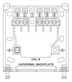
The SSR303 receiver should be located as near as is practical to the device to be controlled, as well as a convenient mains electricity supply. To remove the wall plate from the SSR303, undo the two retaining screws located on the underside, the wall plate should now be easily removed. Once the wall plate has been removed from the packaging please ensure the SSR303 is re-sealed to prevent damage from dust, debris etc.
The wall plate should be fitted with the retaining screws located at the bottom and in a position which allows a total clearance of at least 50mm around the SSR303 receiver.
Direct Wall Mounting
Offer the plate to the wall in the position where the SSR303 is to be mounted and mark the fixing positions through the slots in the wall plate. Drill and plug the wall, then secure the plate into position. The slots in the wall plate will compensate for any misalignment of the fixings.
Wall Box Mounting
The wall plate may be fitted directly on to a single gang flush wiring box complying with BS4662, using two M3.5 screws. The receiver is suitable for mounting on a flat surface only; it is not suitable for mounting on an unearthed metal surface.
Electrical Connections
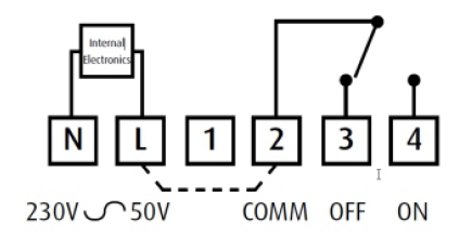
All necessary electrical connections should now be made. Flush wiring can enter from the rear through the aperture in the backplate. The mains supply terminals are intended to be connected to the supply by means of fixed wiring. The receiver is mains powered and requires a 3 Amp fused spur. The recommended cable size is 1.Omm2. The receiver is double insulated and does not require an earth connection, an earth connection block is provided on the backplate for terminating any cable earth conductors. Earth continuity must be maintained and all bare earth conductors must be sleeved. Ensure that no conductors are left protruding outside the central space enclosed by the backplate.
Inclusion/Exclusion
On factory default the device does not belong to any Z-Wave network. The device needs to be added to an existing wireless network to communicate with the devices of this network. This process is called Inclusion.
Devices can also be removed from a network. This process is called Exclusion. Both processes are initiated by the primary controller of the Z-Wave network. This controller is turned into exclusion respective inclusion mode. Inclusion and Exclusion is then performed doing a special manual action right on the device.
Inclusion
To confirm inclusion and exclusion push and hold the network button until the "ON" LED starts flashing.
Exclusion
To confirm inclusion and exclusion push and hold the network button until the "ON" LED starts flashing.
Product Usage
The SSR303 receiver unit receives the Z-Wave radio signals from the 3rd party Z-wave controllers. In the unlikely event of a communication failure it is possible to override the system and switch On and Off using the On/Off buttons on the SSR303 receiver as a local override.
If the override is used to override the system when it is functioning correctly then the override will be cancelled by the next switching operation and normal operation will be resumed. In any case, with no further intervention, normal operation will be restored within one hour of the override being operated.
Quick trouble shooting
Here are a few hints for network installation if things dont work as expected.
- Make sure a device is in factory reset state before including. In doubt exclude before include.
- If inclusion still fails, check if both devices use the same frequency.
- Remove all dead devices from associations. Otherwise you will see severe delays.
- Never use sleeping battery devices without a central controller.
- Dont poll FLIRS devices.
- Make sure to have enough mains powered device to benefit from the meshing
Technical Data
| Dimensions | 0.0860000x0.0860000x0.0300000 mm |
| Weight | 140 gr |
| Firmware Version | 01.00 |
| Z-Wave Version | 02.4e |
| Certification ID | ZC08-10120003 |
| Z-Wave Product Id | 0059.0003.0001 |
| Frequency | Europe - 868,4 Mhz |
| Maximum transmission power | 5 mW |
Supported Command Classes
- Basic
- Thermostat Mode
- Manufacturer Specific
- Switch Binary
- Version
Explanation of Z-Wave specific terms
- Controller — is a Z-Wave device with capabilities to manage the network. Controllers are typically Gateways,Remote Controls or battery operated wall controllers.
- Slave — is a Z-Wave device without capabilities to manage the network. Slaves can be sensors, actuators and even remote controls.
- Primary Controller — is the central organizer of the network. It must be a controller. There can be only one primary controller in a Z-Wave network.
- Inclusion — is the process of adding new Z-Wave devices into a network.
- Exclusion — is the process of removing Z-Wave devices from the network.
- Association — is a control relationship between a controlling device and a controlled device.
- Wakeup Notification — is a special wireless message issued by a Z-Wave device to announces that is able to communicate.
- Node Information Frame — is a special wireless message issued by a Z-Wave device to announce its capabilities and functions.