Secure
Timer Controlled Wall Thermostat
SKU: SEC_STP328
Quickstart
This is a
For Inclusion and Exclusion press and hold both white buttons on the device until the LED starts flashing. (green ->Inclusion, red -> Exclusion)
Important safety information
Please read this manual carefully. Failure to follow the recommendations in this manual may be dangerous or may violate the law. The manufacturer, importer, distributor and seller shall not be liable for any loss or damage resulting from failure to comply with the instructions in this manual or any other material. Use this equipment only for its intended purpose. Follow the disposal instructions. Do not dispose of electronic equipment or batteries in a fire or near open heat sources.Product Description
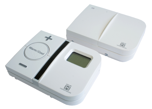
The STP328 is a battery operated wall controller capable controlling a boiler actuator via a Z-Wave wireless connection. The device can act both as primary controller or as secondary controller. The controlling and switching behavior however can not be set wirelessly but with local control buttons only. The device has multipe timers and is therefore able to execute even complex heating scenarios.
The STP328 is supplied in two parts. The actuator (SEC_SSR302) which is hard wired to the combi or conventional system boiler and the thermostat which can be used in any normal domestic environment within a typical 30 metre range without the need for any costly or disruptive wiring.
Installation
Thermostat
The backplate of the device is to be used as a mounting plate for wall mounting. Open the backplate by undoing the screws located on the underside and swing open the control panel. Use the backplate as pattern and mark the drill holes, drill the holes and mount the backplate. The slots in the backplate will compensate for any misalignment of the fixings. Reassemble the control panel with the backplate and swing close it into closed position.
Boiler Actuator
Installation and connection of the receiver should only be carried out by a suitably qualified person.
To remove the backplate from the receiver, undo the two retaining screws located on the underside; the backplate should now be easily removed. Once the backplate has been removed from the packaging, ensure the receiver is re-sealed to prevent damage from dust, debris etc. The backplate should be fitted with the wiring terminals at the top and in a position which allows a total clearance of at least 50mm around the receiver.
Direct Wall Mounting
The receiver should ideally be located near an existing power supply within an easy wiring location to the items being switched. Offer the plate to the wall in the position where the receiver is to be mounted, remembering that the backplate fits to the left hand side of the receiver. Mark the fixing positions through the slots in the backplate, drill and plug the wall, then secure the plate in position. The slots in the backplate will compensate for any misalignment of the fixings.
Wiring Box Mounting
The receiver backplate may be fitted directly onto a single gang steel flush wiring box complying to BS4662 using two M3.5 screws. The receiver is suitable for mounting on a flat surface only. It must not be positioned on an unearthed metal surface.
Electrical Connections
All necessary electrical connections should now be made. Flush wiring can enter from the rear through the aperture in the backplate. Surface wiring can only enter from beneath the receiver and must be securely clamped. The mains supply terminals are intended to be connected to the supply by means of fixed wiring. The receiver is mains powered and requires a 3 amp fused spur. The recommended cable sizes are 1.0mm2 or 1.5mm2.
The receiver is double insulated and does not require an earth connection although an earth connection block is provided on the back plate for terminating any cable earth conductors. Earth continuity must be maintained and all bare earth conductors must be sleeved. Ensure that no conductors are left protruding outside the central space enclosed by the backplate.
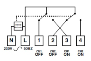
Internal Wiring Diagram
The SSR302 has an integral connection which makes it suitable for mains voltage applications only. No additional linking is required between terminals.
Fitting the Receiver
If surface wiring has been used, remove the knockout/insert from the bottom thermostat to accommodate it. Fit the receiver to the backplate, ensure the lugs on the backplate engage with the slots on the receiver. Swing the bottom of the receiver into position ensuring that the connection pins on the back of the unit locate into the terminal slots in the backplate.
Warning: ISOLATE MAINS SUPPLY BEFORE COMMENCING INSTALLATION!
Product Usage
Thermostat
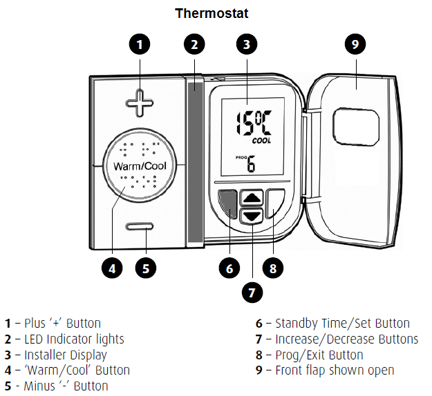
Part 1 - Day to Day operation
The Thermostat has been designed to be a simple to use thermostat, requiring minimal user intervention with a pre-programmed heating profile. Simple temperature adjustments can be easily carried out by using the "+" and "-" buttons. The indicator lights react to any temporary user adjustments, with the LED indicators working in the following way; "Warm" is shown by two red lights and "Cool" is shown by a single blue light. The centre button marked "Warm/Cool" allows you to toggle between the warm and cool settings.
Power Down Mode
During normal operation the Thermostat will go into Power Down Mode, this is to maximise the life of the 3 x AA batteries fitted. Normal operation will continue during this mode, and the heating will be unaffected. The result of the Power Down Mode will mean that the LED indicators will not be displayed and LCD will not be illuminated, although the "Warm" or "Cool" temperature will be displayed. To "wake up" the AS2-RF press the "Warm/Cool" button for 5 seconds, this will then illuminate both the LED and LCD displays for a period. Any adjustment can then be made, the Power Down Mode will commence again approximately 8 seconds after the last button press.
Warm and Cool Temperature Adjustment
The Warm and Cool target temperature settings on the Thermostat are fully adjustable. To change a target temperature it is first necessary to press the centre button to bring up the "Warm" or "Cool" setting (indicated by the red or blue LED indicators). By using the up/down keys under the flap the Warm/Cool temperature can be increased or decreased to the desired temperature setting. PLEASE NOTE - it is not possible to set the warm setting to below that of the cool setting or vice versa. Once a new temperature has been set in either the Warm or Cool setting the Thermostat will continue to use this setting until the next manual adjustment.
Frost Protection
The blue button situated under the flap will initiate the frost protection mode, when pressed the word "STANDBY" will appear on the display, the thermostat has been preprogrammed with a frost protection temperature level of 7C, this can be adjusted by using the up and down arrow buttons. Minimum setting 5C. It is not possible to set a frost protection temperature above the cool setting.
Part 2 - Programming Mode
The Thermostat has been designed for minimal user intervention, however should any changes to the existing programms be required please press button 6 and 8 simultaneously to enter the programming mode, this will allow you to:
- Check the current time/date/year
- Check the current profile
- Set a new pre-set profile or
- Set a user defined profile
PLEASE NOTE: Upon completion of any of the adjustments above, please ensure that you exit the programming mode by pressing buttons 6 and 8 simultaneously.
Time and Date Check
The Thermostat has a built in automatic clock adjusting for BST and GMT time changes and has been preset with the current time and date during manufacture. No alteration should be required to the time and date, however if any modification is required please refer to the steps below.
- Open Cover
- Enter programming mode by pressing buttons 6 and 8
- Press TIME
- Press SET
- MINUTE flashes. Adjust using UP/DOWN buttons. Press SET
- HOUR flashes. Adjust using UP/DOWN buttons. Press SET
- DATE flashes. Adjust using UP/DOWN buttons. Press SET
- MONTH flashes. Adjust using UP/DOWN buttons. Press SET
- YEAR flashes. Adjust using UP/DOWN buttons. Press SET
- Press EXIT
- Exit programming mode by pressing buttons 6 and 8
Setting Heating Profiles
The Thermostat contains a selection of five preset and one user definable profile options, one of these will have been set by the Installer. Care should be taken to ensure a profile is selected that suits your lifestyle the best. If none of the preset profiles meet your requirements it is possible to set a user defined profile.
- Open Cover
- Enter porgramming mode by pressing buttons 6 and 8
- Press PROG
- Press SET
- Select the required profile by using the UP/DOWN buttons
- Press SET. To review preset profiles 1 to 5 press UP button (7) repeatedly
- Press EXIT
- Exit programming mode by pressing buttons 6 and 8
Heating Profiles
The Thermostat has six heating profiles, five are fixed and one is adjustable. Profile "ONE" has been set as the default and is detailed below. During installation a heating profile should have been set to best match your requirements:
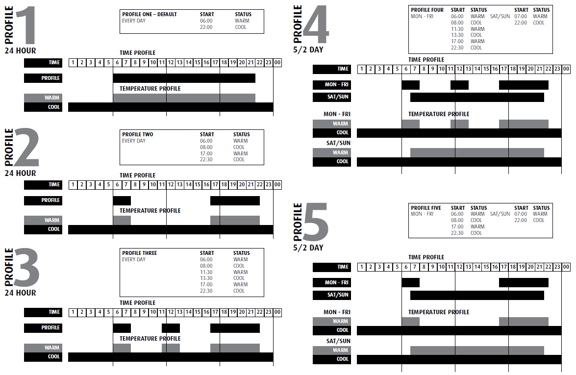
Profiles one to five have fixed periods, no alteration to the Warm/Cool times can be made, if it is necessary to make any alterations then profile six must be used. Profile six will allow you to set up a profile to your exact requirements.
User Definable - 7 Day Programming

Profile 6 will allow you to set up a profile to your exact requirements. By using the flow chart below you can adjust the Warm/Cool timing periods as required. If only one or two Warm/Cool periods are required on any day set the times accordingly and set the remaining Warm and Cool start times to be exactly the same as each other. This will cancel the 2nd or 3rd Warm/Cool periods altogether for the day concerned. Unused periods will be shown by a series of dashes on the settings screen. Press SET and the next day and SET appears in the display. Press SET to adjust the next days settings or EXIT to return to the main menu. To do this press SET until the next day and SET appears in the display. Unused periods will be shown by a series of dashes on the setting screen. If one or two periods have been set and you wish to return to three periods in 24 hours then pressing the up arrow when the dashes appear after the last Cool setting will bring back the hidden Warm/Cool settings.
- Open Cover
- Enter porgramming mode by pressing buttons 6 and 8
- Press PROG
- Press SET
- Select PROFILE SIX by using the UP/DOWN buttons and press SET
- Adjust the WARM start time by using the UP/DOWN buttons and confirming with the SET button
- Adjust the COOL start time by using the UP/DOWN buttons and confirming with the SET button
- Repeat for Periods 2 and 3 (or if not needed equalise the remaining Warm and Cool times to cancel and press SET - see above)
- SET is displayed on the screen 1. To continue programming to the next day press SET and go to "A" 2. To copy the altered settings to the next day press the DOWN button and go to "C" 3. To finish programming go to "D"
- Press COPY and repeat for each day to be copied
- When finished press the DOWN button and go to "B"
- Press EXIT twice and exit programming mode by pressing buttons 6 and 8
Boiler Actuator
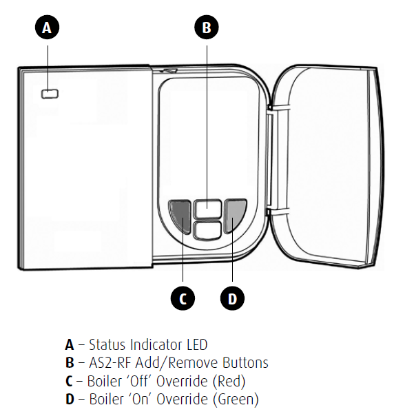
The unit supports two static end points for the two channels.
Pressing the Top White button for 1 second will issue an "end point capability report" for channel 1. Pressing the Bottom White button for 1 second will issue an "end point capability report" for channel 2. Additionally the devices enters learn mode for 1 second. This is useful when to associate / disassociate the device with a control group or just to determine the device and command classes supported. This can be done at any time but will not provide any indication to the operator
Broadcasting in this manner has been implemented to support association of a channel with a 3rd party controller that supports Multi-Channel Command Class.
| Reset to factory default | XXXResetDescription |
| Inclusion | For Inclusion and Exclusion press and hold both white buttons on the device until the LED starts flashing. (green ->Inclusion, red -> Exclusion) |
| Exclusion | For Inclusion and Exclusion press and hold both white buttons on the device until the LED starts flashing. (green ->Inclusion, red -> Exclusion) |
| NIF | Pressing and holding the two white buttons for 1 second will trigger the device to issue a Node Information Frame. |
| Wakeup | XXXWakeupDescription |
| Protection | XXXProtection |
| FirmwareUpdate | XXXFirmwareUpdate |
| SetAssociation | For association press and hold one of the two white buttons on the device for 1 second. |
Association Groups:
| Group Number | Maximum Nodes | Description |
|---|---|---|
| 1 | 5 | Devices controlled by open/close events |
Technical Data
| Dimensions | 0.0900000x0.2420000x0.0340000 mm |
| Weight | 470 gr |
| EAN | 5015914212017 |
| Device Type | Routing Binary Sensor |
| Generic Device Class | Binary Sensor |
| Specific Device Class | Routing Binary Sensor |
| Firmware Version | 01.03 |
| Z-Wave Version | 02.40 |
| Certification ID | ZC07120001 |
| Z-Wave Product Id | 0086.0002.0004 |
| Frequency | Europe - 868,4 Mhz |
| Maximum transmission power | 5 mW |