WiDom
Z-Wave Double Switch
SKU: WIDEWDS

Quickstart
This is a
S WiDom Universal Double Switch is designed for installation in flush mounting boxes, close to the loads to be controlled. A single click on the Z-Wave button will confirm Inclusion and three clicks will confirm Exclusion. Please read carefully the enclosed user manual before installation of the radio-actuator, in order to ensure an error-free functioning. ATTENTION: only authorized technicians under consideration of the country-specific installation guidelines/norms may do works with 230 Volt mains power.
1) Ensure that the main power switch is set in the OFF position
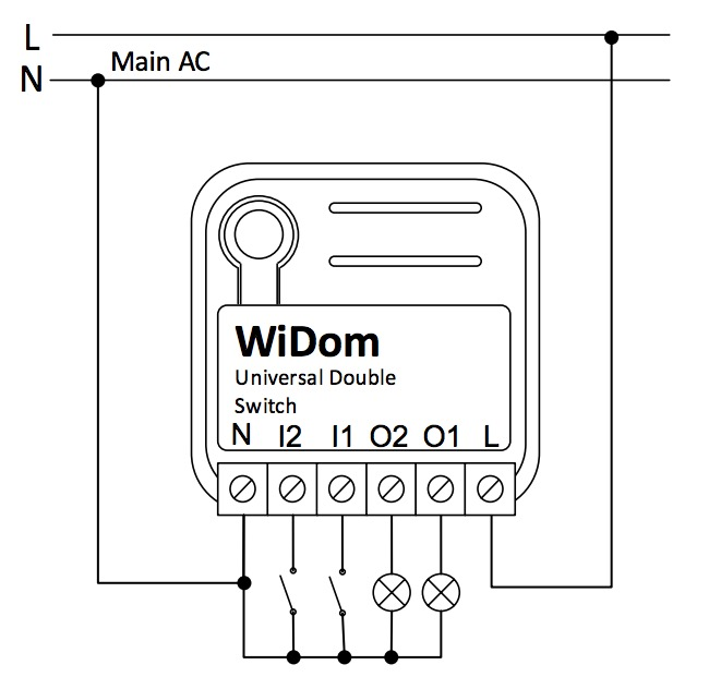
2) Connect the device following the diagrams provided
3) Include the device into the Z-Wave network
4) Shut the electrical box containing the device
5) Turn the main power switch back on
Important safety information
Please read this manual carefully. Failure to follow the recommendations in this manual may be dangerous or may violate the law. The manufacturer, importer, distributor and seller shall not be liable for any loss or damage resulting from failure to comply with the instructions in this manual or any other material. Use this equipment only for its intended purpose. Follow the disposal instructions. Do not dispose of electronic equipment or batteries in a fire or near open heat sources.What is Z-Wave?
Z-Wave is the international wireless protocol for communication in the Smart Home. This device is suited for use in the region mentioned in the Quickstart section.
Z-Wave ensures a reliable communication by reconfirming every message (two-way communication) and every mains powered node can act as a repeater for other nodes (meshed network) in case the receiver is not in direct wireless range of the transmitter.
This device and every other certified Z-Wave device can be used together with any other certified Z-Wave device regardless of brand and origin as long as both are suited for the same frequency range.
If a device supports secure communication it will communicate with other devices secure as long as this device provides the same or a higher level of security. Otherwise it will automatically turn into a lower level of security to maintain backward compatibility.
For more information about Z-Wave technology, devices, white papers etc. please refer to www.z-wave.info.
Product Description
Universal Double Switch is an ON/OFF control device designed to independently control two separate loads, suited for use as both a local and remote switch. Each of its two channels features an integrated consumption measurement device. The Universal Double Switch also boasts the lowest energy consumption on the market.
Prepare for Installation / Reset
Please read the user manual before installing the product.
In order to include (add) a Z-Wave device to a network it must be in factory default state. Please make sure to reset the device into factory default. You can do this by performing an Exclusion operation as described below in the manual. Every Z-Wave controller is able to perform this operation however it is recommended to use the primary controller of the previous network to make sure the very device is excluded properly from this network.
Safety Warning for Mains Powered Devices
ATTENTION: only authorized technicians under consideration of the country-specific installation guidelines/norms may do works with mains power. Prior to the assembly of the product, the voltage network has to be switched off and ensured against re-switching.
Installation
INFO: WiDom Universal Double Switch is designed for installation in flush mounting boxes, close to the loads to be controlled.
WARNING: WiDom Universal Double Switch must be installed by electricians qualified to operate on electrical systems in compliance with safety requirements set out by current regulations.
DANGER: WiDom Universal Double Switch must be connected to 230V AC voltage mains supplies; please ensure that the general switch is in the OFF position prior to carrying out any operation.
DANGER: Any operation requiring the use of service button (B) must only be carried out during the installation phase and must be considered as a service procedure to be performed by qualified personnel. This operation must be carried out by adopting all necessary precautions to operate on areas with a single level of isolation.
WARNING: Do not connect loads exceeding the maximum power load permitted by the relay contacts.
WARNING: All connections must be performed according to the electrical diagrams provided.
WARNING: WiDom Universal Double Switch must be installed in norm-compliant systems suitably protected from overloads and short circuits.
TIP: The antenna must not be shortened, removed or modified. To ensure maximum efficiency, it must be installed as shown. Large size metal equipment near the antenna can negatively affect reception. Each WiDom device is a node in a mesh network. If there are metal obstacles, the obstacle can often be overcome with a further triangulation node.
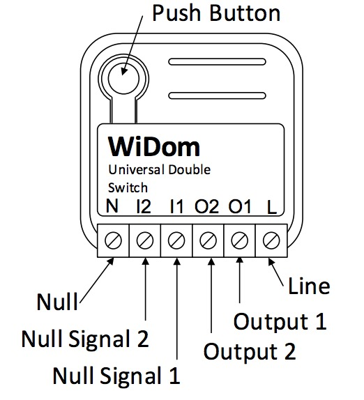
- L) Phase connection terminal
- N) Neutral connection terminal
- I1) Neutral signal to activate the output 1
- I2) Neutral signal to activate the output 2
- O1) Phase Output 1 referred to Neutral
- O2) Phase Output 2 referred to Neutral
Inclusion/Exclusion
On factory default the device does not belong to any Z-Wave network. The device needs to be added to an existing wireless network to communicate with the devices of this network. This process is called Inclusion.
Devices can also be removed from a network. This process is called Exclusion. Both processes are initiated by the primary controller of the Z-Wave network. This controller is turned into exclusion respective inclusion mode. Inclusion and Exclusion is then performed doing a special manual action right on the device.
Inclusion
- 1 click on the Z-Wave Button to confirm inclusion of the device.
- 3 clicks on the Z-Wave Button to confirm exclusion of the device.
- 6 clicks on the Z-Wave Button to confirm reset to factory settings.
Exclusion
- 1 click on the Z-Wave Button to confirm inclusion of the device.
- 3 clicks on the Z-Wave Button to confirm exclusion of the device.
- 6 clicks on the Z-Wave Button to confirm reset to factory settings.
Product Usage
If the device was successfully included it will apear in your SmartHome Software.
WiDom Universal Double Switch can control other devices such as relays or dimmers.
Node Information Frame
The Node Information Frame (NIF) is the business card of a Z-Wave device. It contains information about the device type and the technical capabilities. The inclusion and exclusion of the device is confirmed by sending out a Node Information Frame. Beside this it may be needed for certain network operations to send out a Node Information Frame. To issue a NIF execute the following action:
Single press the Z-Wave Button to send out a Node Information Frame.
Quick trouble shooting
Here are a few hints for network installation if things dont work as expected.
- Make sure a device is in factory reset state before including. In doubt exclude before include.
- If inclusion still fails, check if both devices use the same frequency.
- Remove all dead devices from associations. Otherwise you will see severe delays.
- Never use sleeping battery devices without a central controller.
- Dont poll FLIRS devices.
- Make sure to have enough mains powered device to benefit from the meshing
Association - one device controls an other device
Z-Wave devices control other Z-Wave devices. The relationship between one device controlling another device is called association. In order to control a different device, the controlling device needs to maintain a list of devices that will receive controlling commands. These lists are called association groups and they are always related to certain events (e.g. button pressed, sensor triggers, ...). In case the event happens all devices stored in the respective association group will receive the same wireless command wireless command, typically a 'Basic Set' Command.
Association Groups:
| Group Number | Maximum Nodes | Description |
|---|---|---|
| 1 | 8 | LifeLine: Devices to receive notifications on: status changes; instantaneous power level; device local reset |
| 2 | 8 | On/Off control (Switch 1) |
| 3 | 8 | Dimming control (Switch 1) |
| 4 | 8 | On/Off control (Switch 2) |
| 5 | 8 | Dimming control (Switch 2) |
Configuration Parameters
Z-Wave products are supposed to work out of the box after inclusion, however certain configuration can adapt the function better to user needs or unlock further enhanced features.
IMPORTANT: Controllers may only allow configuring signed values. In order to set values in the range 128 ... 255 the value sent in the application shall be the desired value minus 256. For example: To set a parameter to 200 it may be needed to set a value of 200 minus 256 = minus 56. In case of a two byte value the same logic applies: Values greater than 32768 may needed to be given as negative values too.
Parameter 1: Outputs Status 1 Click
Defines the status of the output O1/O2 when the switch connected to I1/I2 receives 1 Click. Size: 1 Byte, Default Value: 1
| Setting | Description |
|---|---|
| 1 | TOGGLE |
| 2 | ON: If the initial status is OFF the system switches to ON; conversely, it maintains its status (ON). |
| 3 | OFF: If the initial status is ON the system switches to OFF; conversely, it maintains its status (OFF). |
| 4 | IGNORE: The device maintains the initial status |
Parameter 2: Output Status 2 Clicks
Defines the status of the output O1/O2 when the switch connected to I1/I2 receives 2 Click. Size: 1 Byte, Default Value: 1
| Setting | Description |
|---|---|
| 1 | TOGGLE |
| 2 | ON: If the initial status is OFF the system switches to ON; conversely, it maintains its status (ON). |
| 3 | OFF: If the initial status is ON the system switches to OFF; conversely, it maintains its status (OFF). |
| 4 | IGNORE: The device maintains the initial status |
Parameter 3: Type of outputs
Defines if the outputs are controlled individually, as a traditional device with two channels, or if its behaviour simulates a single pole double throw relay. Size: 1 Byte, Default Value: 0
| Setting | Description |
|---|---|
| 0 | SINGLE CHANNELS: Channel 1 and Channel 2 are controlled individually |
| 1 - 127 | SINGLE POLE DOUBLE THROW RELAY: The two channels are in opposite status. If the Channel 1 is close the Channel 2 is open, if the Channel 1 is open the Channel 2 is close. The value of the parameter defines the closing delay of the relay in tenth of seconds |
Parameter 4: Number of clicks that activate the control of the associated devices
Defines the number of clicks on the Switch 1 or Switch 2 that enable the control of the correspondent associated devices. Size: 1 Byte, Default Value: 2
| Setting | Description |
|---|---|
| 1 | Associated devices are controlled by 1 Click on the correspondent external switch |
| 2 | Associated devices are controlled by 2 Clicks on the correspondent external switch |
Parameter 5: Level used to control the devices associated to group 2 and 3
Defines how to control the devices associated to group 2 and 3. Size: 1 Byte, Default Value: 100
| Setting | Description |
|---|---|
| 0 | The associated devices are switched OFF |
| 255 | The associated devices are switched ON |
| 1 - 99 | The associated devices (dimmer, roller shutters) are set to the indicated level (only for devices associated to group 3) |
| 100 | If the Relay 1 is ON/OFF, the associated devices are ON/OFF |
| 101 | If the Relay 1 is ON the associated devices are ON; if it is OFF no action is taken on the associated devices |
| 102 | If the Relay 1 is OFF the associated devices are OFF; if it is ON no action is taken on the associated devices |
| 103 | If the Relay 1 is ON the associated devices are OFF; if it is OFF no action is taken on the associated devices |
| 104 | If the Relay 1 is OFF the associated devices are ON; if it is ON no action is taken on the associated devices |
| 105 | If the Relay 1 is ON/OFF, the associated devices are OFF/ON |
| 106 | No action is taken on the associated devices |
Parameter 6: Level used to control the devices associated to group 4 and 5
Defines how to control the devices associated to group 4 and 5. Size: 1 Byte, Default Value: 100
| Setting | Description |
|---|---|
| 0 | The associated devices are switched OFF |
| 255 | The associated devices are switched ON |
| 1 - 99 | The associated devices (dimmer, roller shutters) are set to the indicated level (only for devices associated to group 5) |
| 100 | If the Relay 2 is ON/OFF, the associated devices are ON/OFF |
| 101 | If the Relay 2 is ON the associated devices are ON; if it is OFF no action is taken on the associated devices |
| 102 | If the Relay 2 is OFF the associated devices are OFF; if it is ON no action is taken on the associated devices |
| 103 | If the Relay 2 is ON the associated devices are OFF; if it is OFF no action is taken on the associated devices |
| 104 | If the Relay 2 is OFF the associated devices are ON; if it is ON no action is taken on the associated devices |
| 105 | If the Relay 2 is ON/OFF, the associated devices are OFF/ON |
| 106 | No action is taken on the associated devices |
Parameter 10: Timer to switch ON the Channel 1
Defines the time after which the Channel 1 is switched ON. Size: 2 Byte, Default Value: 0
| Setting | Description |
|---|---|
| 0 | Timer disabled |
| 1 - 32000 | After this time the relay of the Channel 1 is ON |
Parameter 11: Timer to switch ON the Channel 2
Defines the time after which the Channel 2 is switched ON. Size: 2 Byte, Default Value: 0
| Setting | Description |
|---|---|
| 0 | Timer disabled |
| 1 - 32000 | After this time the relay of the Channel 2 is ON |
Parameter 12: Timer to switch OFF the Channel 1
Defines the time after which the Channel 1 is switched OFF. Size: 2 Byte, Default Value: 0
| Setting | Description |
|---|---|
| 0 | Timer disabled |
| 1 - 32000 | After this time the relay of the Channel 1 is OFF |
Parameter 13: Timer to switch OFF the Channel 2
Defines the time after which the Channel 2 is switched OFF. Size: 2 Byte, Default Value: 0
| Setting | Description |
|---|---|
| 0 | Timer disabled |
| 1 - 32000 | After this time the relay of the Channel 2 is OFF |
Parameter 20: Outputs status upon receipt of a Multi-Channel Basic Set command
The two channels can be controlled individually by Z-Wave network. The status of the channels upon receipt of a Multi-Channel Basic Set command is defined by the value set on the parameter. Size: 1 Byte, Default Value: 1
| Setting | Description |
|---|---|
| 1 | AS RECEIVED |
| 2 | IGNORE IF ON |
| 3 | IGNORE IF OFF |
| 4 | IGNORE |
Parameter 21: Outputs status upon receipt of a Basic Set command
The channels of the device can be controlled individually from all other Z-Wave devices that support the multichannel feature. In order to support also the integration with no-multichannel systems, this parameter allows to define if the receipt of a no-multichannel command controls only the Channel 1 or both. Size: 1 Byte, Default Value: 3
| Setting | Description |
|---|---|
| 1 | The receipt of a Basic Set ON/OFF set the Channel 1 to ON/OFF |
| 3 | The receipt of a Basic Set ON/OFF set both the Channel 1 and the Channel 2 to ON/OFF |
Parameter 60: Start-up status
Defines the status of the device following a restart. Size: 1 Byte, Default Value: 4
| Setting | Description |
|---|---|
| 0 | Both Relay 1 and Relay 2 OFF |
| 1 | Relay 1 ON, Relay 2 OFF |
| 2 | Relay 1 OFF, Relay 2 ON |
| 3 | Both Relay 1 and Relay 2 ON |
| 4 | PREVIOUS STATUS: Status prior to restart |
Parameter 61: Configuration reset
Defines which parameters should be reset to default values. Size: 1 Byte, Default Value: 4
| Setting | Description |
|---|---|
| 0 | The device is reset to the original factory settings |
| 1 | All associations and only the associations are reset |
| 2 | The associations are maintained while all other configuration parameters are reset to the original factory settings, except for the specific configuration. |
| 3 | The device will be restarted |
| 4 | No action is performed |
Parameter 62: Type of external switch
Defines the type of external switch connected to the device. Size: 1 Byte, Default Value: 4
| Setting | Description |
|---|---|
| 0 | The actions on the external switch are ignored. In this mode, the device can only be controlled via the network. |
| 1 | The external switch is a normally open button |
| 2 | The external switch is a traditional switch |
| 4 | After the first single click on the external switch, the system automatically determines the type of external switch used and sets the parameter with the new value accordingly. |
Technical Data
| Dimensions | 0.0370000x0.0370000x0.0170000 mm |
| Weight | 28.2 gr |
| Hardware Platform | ZM5202 |
| EAN | 8059265060047 |
| IP Class | IP 20 |
| Voltage | 230 V |
| Load | 10 A |
| Device Type | On/Off Power Switch |
| Generic Device Class | Binary Switch |
| Specific Device Class | Binary Power Switch |
| Firmware Version | 01.28 |
| Z-Wave Version | 04.05 |
| Certification ID | ZC10-15115003 |
| Z-Wave Product Id | 0x0149.0x1214.0x0504 |
| Frequency | Europe - 868,4 Mhz |
| Maximum transmission power | 5 mW |
Supported Command Classes
- Basic
- Switch Binary
- Switch All
- Meter
- Association Grp Info
- Device Reset Locally
- Zwaveplus Info
- Multi Channel
- Configuration
- Manufacturer Specific
- Powerlevel
- Association
- Version
- Multi Channel Association
- Firmware Update Md
Controlled Command Classes
- Basic
- Switch Binary
- Device Reset Locally
Explanation of Z-Wave specific terms
- Controller — is a Z-Wave device with capabilities to manage the network. Controllers are typically Gateways,Remote Controls or battery operated wall controllers.
- Slave — is a Z-Wave device without capabilities to manage the network. Slaves can be sensors, actuators and even remote controls.
- Primary Controller — is the central organizer of the network. It must be a controller. There can be only one primary controller in a Z-Wave network.
- Inclusion — is the process of adding new Z-Wave devices into a network.
- Exclusion — is the process of removing Z-Wave devices from the network.
- Association — is a control relationship between a controlling device and a controlled device.
- Wakeup Notification — is a special wireless message issued by a Z-Wave device to announces that is able to communicate.
- Node Information Frame — is a special wireless message issued by a Z-Wave device to announce its capabilities and functions.