Widom
Smart TE Dimmer
SKU: WIDEWTD


Quickstart
This is a
Press any sequence of click on the integrated button
Important safety information
Please read this manual carefully. Failure to follow the recommendations in this manual may be dangerous or may violate the law. The manufacturer, importer, distributor and seller shall not be liable for any loss or damage resulting from failure to comply with the instructions in this manual or any other material. Use this equipment only for its intended purpose. Follow the disposal instructions. Do not dispose of electronic equipment or batteries in a fire or near open heat sources.What is Z-Wave?
Z-Wave is the international wireless protocol for communication in the Smart Home. This device is suited for use in the region mentioned in the Quickstart section.
Z-Wave ensures a reliable communication by reconfirming every message (two-way communication) and every mains powered node can act as a repeater for other nodes (meshed network) in case the receiver is not in direct wireless range of the transmitter.
This device and every other certified Z-Wave device can be used together with any other certified Z-Wave device regardless of brand and origin as long as both are suited for the same frequency range.
If a device supports secure communication it will communicate with other devices secure as long as this device provides the same or a higher level of security. Otherwise it will automatically turn into a lower level of security to maintain backward compatibility.
For more information about Z-Wave technology, devices, white papers etc. please refer to www.z-wave.info.
Product Description
It operates in any Z-Wave network with other Z-Wave/Z-Wave Plus certified devices and controllers from any other manufacturer. As a constantly powered node, WiDom Smart TE Dimmer will act as repeater regardless of the vendor in order to increase the reliability of the network.
Prepare for Installation / Reset
Please read the user manual before installing the product.
In order to include (add) a Z-Wave device to a network it must be in factory default state. Please make sure to reset the device into factory default. You can do this by performing an Exclusion operation as described below in the manual. Every Z-Wave controller is able to perform this operation however it is recommended to use the primary controller of the previous network to make sure the very device is excluded properly from this network.
Reset to factory default
This device also allows to be reset without any involvement of a Z-Wave controller. This procedure should only be used when the primary controller is inoperable.
Press 6 times the integrated button
Safety Warning for Mains Powered Devices
ATTENTION: only authorized technicians under consideration of the country-specific installation guidelines/norms may do works with mains power. Prior to the assembly of the product, the voltage network has to be switched off and ensured against re-switching.
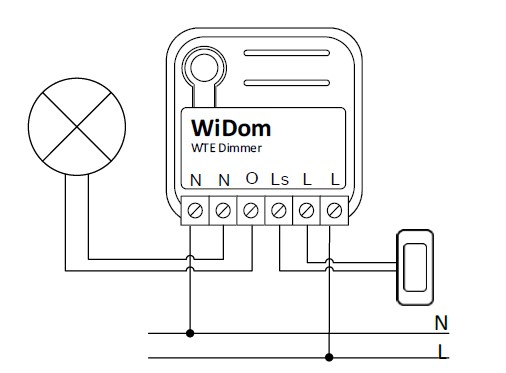
Installation
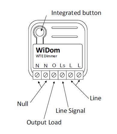
Electrical connections diagram
Inclusion/Exclusion
On factory default the device does not belong to any Z-Wave network. The device needs to be added to an existing wireless network to communicate with the devices of this network. This process is called Inclusion.
Devices can also be removed from a network. This process is called Exclusion. Both processes are initiated by the primary controller of the Z-Wave network. This controller is turned into exclusion respective inclusion mode. Inclusion and Exclusion is then performed doing a special manual action right on the device.
Inclusion
Press any sequence of click on the integrated buttonExclusion
Press any sequence of click on the integrated buttonProduct Usage
Solid RED: the device is not included in any network
TIP: To test if the electrical connections are correct, before the inclusion of the device, while pressing n times the external switch, the RGB LED should flash green for the same amount of times. If it does not, check the wire connections.
Overheat protection mode
Quick trouble shooting
Here are a few hints for network installation if things dont work as expected.
- Make sure a device is in factory reset state before including. In doubt exclude before include.
- If inclusion still fails, check if both devices use the same frequency.
- Remove all dead devices from associations. Otherwise you will see severe delays.
- Never use sleeping battery devices without a central controller.
- Dont poll FLIRS devices.
- Make sure to have enough mains powered device to benefit from the meshing
Association - one device controls an other device
Z-Wave devices control other Z-Wave devices. The relationship between one device controlling another device is called association. In order to control a different device, the controlling device needs to maintain a list of devices that will receive controlling commands. These lists are called association groups and they are always related to certain events (e.g. button pressed, sensor triggers, ...). In case the event happens all devices stored in the respective association group will receive the same wireless command wireless command, typically a 'Basic Set' Command.
Association Groups:
| Group Number | Maximum Nodes | Description |
|---|---|---|
| 1 | 8 | Lifeline |
| 2 | 8 | Dimming |
Configuration Parameters
Z-Wave products are supposed to work out of the box after inclusion, however certain configuration can adapt the function better to user needs or unlock further enhanced features.
IMPORTANT: Controllers may only allow configuring signed values. In order to set values in the range 128 ... 255 the value sent in the application shall be the desired value minus 256. For example: To set a parameter to 200 it may be needed to set a value of 200 minus 256 = minus 56. In case of a two byte value the same logic applies: Values greater than 32768 may needed to be given as negative values too.
Parameter 1: Start-up Status
Defines the status of the device, in term of light level, following a restart. Size: 1 Byte, Default Value: 255
| Setting | Description |
|---|---|
| 0 - 99 | 0-99% dimming level after device restart |
| 255 | At devices restart it restores the same dimming level at the moment of power failure. |
Parameter 2: Fade On Time
Defines the time spent to switch the load from complete OFF to complete ON. Size: 1 Byte, Default Value: 1
| Setting | Description |
|---|---|
| 1 - 127 | Expresses in seconds the time spent to switch the load from complete OFF to complete ON |
| 128 - 255 | Expresses in minutes the time spent to switch the load from complete OFF to complete ON |
Parameter 3: Fade Off Time
Defines the time spent to switch the load from complete ON to complete OFF. Size: 1 Byte, Default Value: 1
| Setting | Description |
|---|---|
| 1 - 127 | Expresses in seconds the time spent to switch the load from complete ON to complete OFF |
| 128 - 255 | Expresses in minutes the time spent to switch the load from complete ON to complete OFF |
Parameter 4: Local Dimming Time
Defines the time spent to switch the controlled load when the external switch is hold down. Size: 1 Byte, Default Value: 5
| Setting | Description |
|---|---|
| 0 | Applies the timing spent to switch the controlled load to Fade On and Fade Off as defined in parameters 2 and 3. |
| 1 - 60 | Expresses in seconds the time spent to switch the load |
Parameter 10: Minimum Light Level
Defines the light level that will correspond to the 1% of dimming. Size: 1 Byte, Default Value: 1
| Setting | Description |
|---|---|
| 1 - 98 | Defines which light level will correspond to 1% in the range between 1 and 98% |
Parameter 11: Maximum Light Level
Defines the light level that will correspond to the 99% of dimming. Size: 1 Byte, Default Value: 99
| Setting | Description |
|---|---|
| 2 - 99 | Defines which light level will correspond to 99% in the range between 2 and 99% |
Parameter 20: Dimmable Load
Define if the connected loads are dimmable or not. Size: 1 Byte, Default Value: 1
| Setting | Description |
|---|---|
| 0 | Any dim level value greater than 0 will set the load to full load. Fade On and Fade Off are considered as 0 seconds. |
| 1 | The load can be controlled as dimmable load |
Parameter 62: Type of external switch
Defines the type of external switch connected to the device. Size: 1 Byte, Default Value: 1
| Setting | Description |
|---|---|
| 0 | The actions on the external switch are ignored. In this mode, the device can only be controlled through the network. |
| 1 | The external switch is a momentary switch type |
| 2 | The external switch is a traditional switch (toggle switch) |
Technical Data
| Dimensions | 37x37x17 mm |
| Weight | 23.23 gr |
| Hardware Platform | ZM5101 |
| EAN | 8059265060085 |
| IP Class | IP 20 |
| Voltage | 230 V |
| Load | 300 W |
| Device Type | Dimmer |
| Generic Device Class | Multilevel Switch |
| Specific Device Class | Routing Multilevel Switch |
| Firmware Version | 01.03 |
| Z-Wave Version | 06.04 |
| Z-Wave Product Id | 0x0149.0x1214.0x0a00 |
| Frequency | Europe - 868,4 Mhz |
| Maximum transmission power | 5 mW |
Supported Command Classes
- Basic
- Switch Multilevel
- Meter
- Association Grp Info
- Device Reset Locally
- Zwaveplus Info
- Supervision
- Configuration
- Manufacturer Specific
- Powerlevel
- Firmware Update Md
- Association
- Version
- Multi Channel Association
- Security
- Transport Service
- Security 2
Controlled Command Classes
- Transport Service
- Security 2
Explanation of Z-Wave specific terms
- Controller — is a Z-Wave device with capabilities to manage the network. Controllers are typically Gateways,Remote Controls or battery operated wall controllers.
- Slave — is a Z-Wave device without capabilities to manage the network. Slaves can be sensors, actuators and even remote controls.
- Primary Controller — is the central organizer of the network. It must be a controller. There can be only one primary controller in a Z-Wave network.
- Inclusion — is the process of adding new Z-Wave devices into a network.
- Exclusion — is the process of removing Z-Wave devices from the network.
- Association — is a control relationship between a controlling device and a controlled device.
- Wakeup Notification — is a special wireless message issued by a Z-Wave device to announces that is able to communicate.
- Node Information Frame — is a special wireless message issued by a Z-Wave device to announce its capabilities and functions.