Widom
Smart TE Dimmer
SKU: WIDEWTD


Quickstart
This is a
Press any sequence of click on the integrated button
Important safety information
Please read this manual carefully. Failure to follow the recommendations in this manual may be dangerous or may violate the law. The manufacturer, importer, distributor and seller shall not be liable for any loss or damage resulting from failure to comply with the instructions in this manual or any other material. Use this equipment only for its intended purpose. Follow the disposal instructions. Do not dispose of electronic equipment or batteries in a fire or near open heat sources.Product Description
It operates in any Z-Wave network with other Z-Wave/Z-Wave Plus certified devices and controllers from any other manufacturer. As a constantly powered node, WiDom Smart TE Dimmer will act as repeater regardless of the vendor in order to increase the reliability of the network.
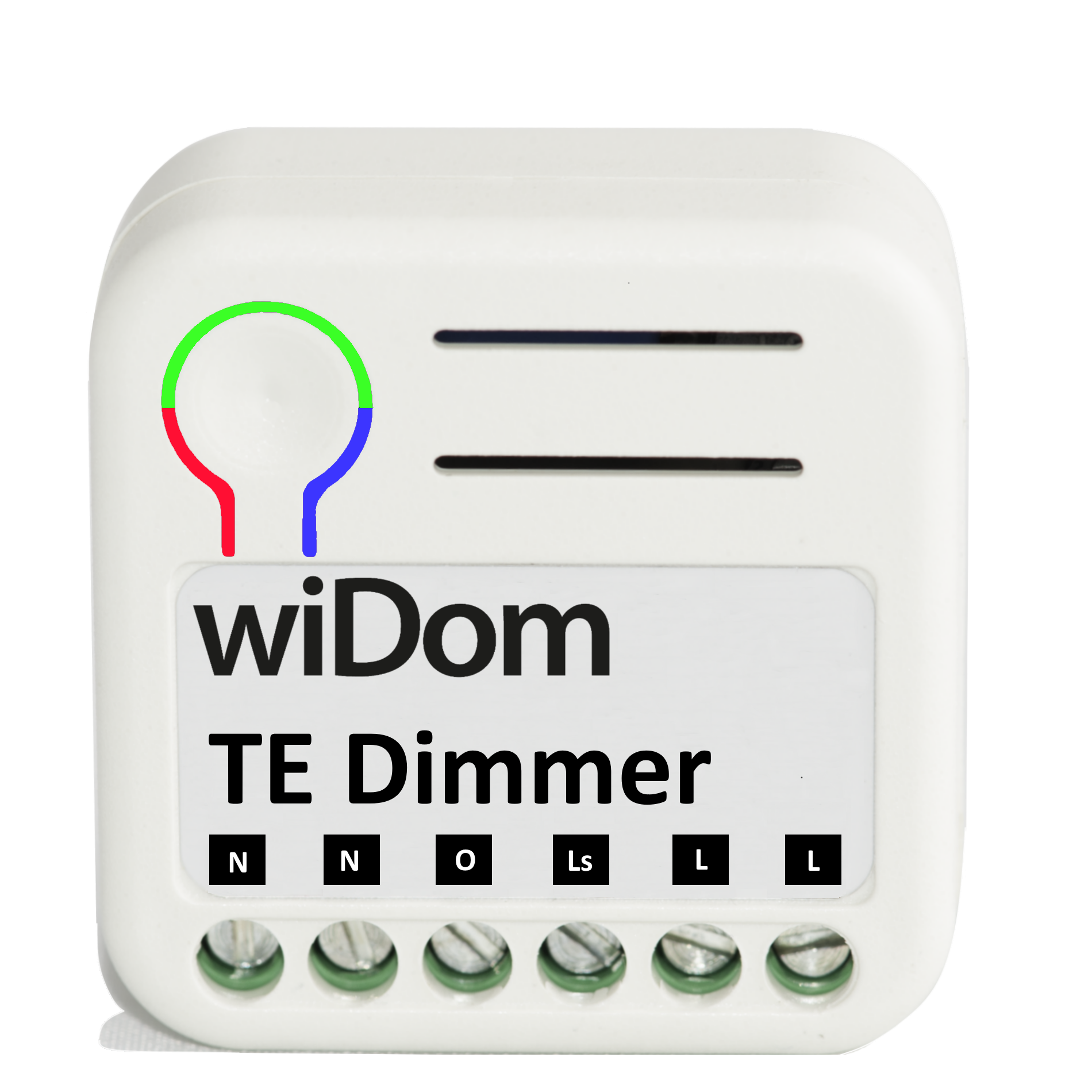
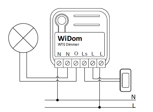
Installation
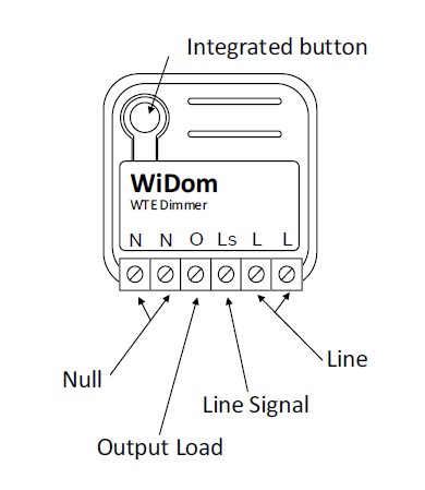
Electrical connections diagram
Product Usage
Solid RED: the device is not included in any network
TIP: To test if the electrical connections are correct, before the inclusion of the device, while pressing n times the external switch, the RGB LED should flash green for the same amount of times. If it does not, check the wire connections.
Overheat protection mode
| Reset to factory default | Press 6 times the integrated button |
| Inclusion | Press any sequence of click on the integrated button |
| Exclusion | Press any sequence of click on the integrated button |
| NIF | XXXNIF |
| Wakeup | XXXWakeupDescription |
| Protection | XXXProtection |
| FirmwareUpdate | XXXFirmwareUpdate |
| SetAssociation | XXXSetAssociation |
Association Groups:
| Group Number | Maximum Nodes | Description |
|---|---|---|
| 1 | 8 | Lifeline |
| 2 | 8 | Dimming |
Configuration Parameters
Parameter 1: Start-up Status
Defines the status of the device, in term of light level, following a restart. Size: 1 Byte, Default Value: 255
| Setting | Description |
|---|---|
| 0 - 99 | 0-99% dimming level after device restart |
| 255 | At devices restart it restores the same dimming level at the moment of power failure. |
Parameter 2: Fade On Time
Defines the time spent to switch the load from complete OFF to complete ON. Size: 1 Byte, Default Value: 1
| Setting | Description |
|---|---|
| 1 - 127 | Expresses in seconds the time spent to switch the load from complete OFF to complete ON |
| 128 - 255 | Expresses in minutes the time spent to switch the load from complete OFF to complete ON |
Parameter 3: Fade Off Time
Defines the time spent to switch the load from complete ON to complete OFF. Size: 1 Byte, Default Value: 1
| Setting | Description |
|---|---|
| 1 - 127 | Expresses in seconds the time spent to switch the load from complete ON to complete OFF |
| 128 - 255 | Expresses in minutes the time spent to switch the load from complete ON to complete OFF |
Parameter 4: Local Dimming Time
Defines the time spent to switch the controlled load when the external switch is hold down. Size: 1 Byte, Default Value: 5
| Setting | Description |
|---|---|
| 0 | Applies the timing spent to switch the controlled load to Fade On and Fade Off as defined in parameters 2 and 3. |
| 1 - 60 | Expresses in seconds the time spent to switch the load |
Parameter 10: Minimum Light Level
Defines the light level that will correspond to the 1% of dimming. Size: 1 Byte, Default Value: 1
| Setting | Description |
|---|---|
| 1 - 98 | Defines which light level will correspond to 1% in the range between 1 and 98% |
Parameter 11: Maximum Light Level
Defines the light level that will correspond to the 99% of dimming. Size: 1 Byte, Default Value: 99
| Setting | Description |
|---|---|
| 2 - 99 | Defines which light level will correspond to 99% in the range between 2 and 99% |
Parameter 20: Dimmable Load
Define if the connected loads are dimmable or not. Size: 1 Byte, Default Value: 1
| Setting | Description |
|---|---|
| 0 | Any dim level value greater than 0 will set the load to full load. Fade On and Fade Off are considered as 0 seconds. |
| 1 | The load can be controlled as dimmable load |
Parameter 62: Type of external switch
Defines the type of external switch connected to the device. Size: 1 Byte, Default Value: 1
| Setting | Description |
|---|---|
| 0 | The actions on the external switch are ignored. In this mode, the device can only be controlled through the network. |
| 1 | The external switch is a momentary switch type |
| 2 | The external switch is a traditional switch (toggle switch) |
Technical Data
| Dimensions | 37x37x17 mm |
| Weight | 23.23 gr |
| Hardware Platform | ZM5101 |
| EAN | 8059265060085 |
| IP Class | IP 20 |
| Voltage | 230 V |
| Load | 300 W |
| Device Type | Dimmer |
| Generic Device Class | Multilevel Switch |
| Specific Device Class | Routing Multilevel Switch |
| Firmware Version | 01.03 |
| Z-Wave Version | 06.04 |
| Z-Wave Product Id | 0x0149.0x1214.0x0a00 |
| Frequency | Europe - 868,4 Mhz |
| Maximum transmission power | 5 mW |