Zipato
RFID Keypad
SKU: ZIPERFID
Quickstart
This is a
Important safety information
Please read this manual carefully. Failure to follow the recommendations in this manual may be dangerous or may violate the law. The manufacturer, importer, distributor and seller shall not be liable for any loss or damage resulting from failure to comply with the instructions in this manual or any other material. Use this equipment only for its intended purpose. Follow the disposal instructions. Do not dispose of electronic equipment or batteries in a fire or near open heat sources.What is Z-Wave?
Z-Wave is the international wireless protocol for communication in the Smart Home. This device is suited for use in the region mentioned in the Quickstart section.
Z-Wave ensures a reliable communication by reconfirming every message (two-way communication) and every mains powered node can act as a repeater for other nodes (meshed network) in case the receiver is not in direct wireless range of the transmitter.
This device and every other certified Z-Wave device can be used together with any other certified Z-Wave device regardless of brand and origin as long as both are suited for the same frequency range.
If a device supports secure communication it will communicate with other devices secure as long as this device provides the same or a higher level of security. Otherwise it will automatically turn into a lower level of security to maintain backward compatibility.
For more information about Z-Wave technology, devices, white papers etc. please refer to www.z-wave.info.
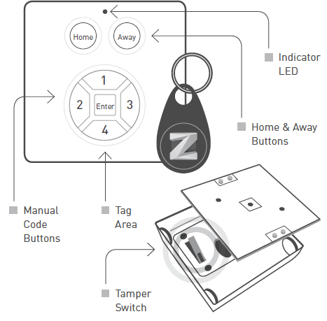
Product Description
Prepare for Installation / Reset
Please read the user manual before installing the product.
In order to include (add) a Z-Wave device to a network it must be in factory default state. Please make sure to reset the device into factory default. You can do this by performing an Exclusion operation as described below in the manual. Every Z-Wave controller is able to perform this operation however it is recommended to use the primary controller of the previous network to make sure the very device is excluded properly from this network.
Safety Warning for Batteries
The product contains batteries. Please remove the batteries when the device is not used. Do not mix batteries of different charging level or different brands.
Installation
Inclusion/Exclusion
On factory default the device does not belong to any Z-Wave network. The device needs to be added to an existing wireless network to communicate with the devices of this network. This process is called Inclusion.
Devices can also be removed from a network. This process is called Exclusion. Both processes are initiated by the primary controller of the Z-Wave network. This controller is turned into exclusion respective inclusion mode. Inclusion and Exclusion is then performed doing a special manual action right on the device.
Inclusion
Exclusion
Press and hold the tamper for 1 seconds and release to start the exclusion process (indication mode: Ready for learn mode).Product Usage
LED Indicator
The indicator gives various statuses of the device as follows:
CONTROL
There are two types of Access Control with User Codes:
There are some situations:
2 | IN CASE A KNOWN MANUAL CODE OR TAG IS PRESENTED. This means, this code was previously SET using the USER_CODE_ SET command. Then the Mini Keypad RFiD/Z-Wave will respond with a ALARM_REPORT_V2 with Type 6 and Event 0x05 or 0x06. When the user presses Home, event 0x06 (Keypad Unlock) will be used. When the user presses Away, event 0x05 (Keypad Lock) will be used.
AFTER THIS THERE ARE TWO POSSIBILITIES:
Communication to a Sleeping device (Wakeup)
This device is battery operated and turned into deep sleep state most of the time to save battery life time. Communication with the device is limited. In order to communicate with the device, a static controller C is needed in the network. This controller will maintain a mailbox for the battery operated devices and store commands that can not be received during deep sleep state. Without such a controller, communication may become impossible and/or the battery life time is significantly decreased.
This device will wakeup regularly and announce the wakeup state by sending out a so called Wakeup Notification. The controller can then empty the mailbox. Therefore, the device needs to be configured with the desired wakeup interval and the node ID of the controller. If the device was included by a static controller this controller will usually perform all necessary configurations. The wakeup interval is a tradeoff between maximal battery life time and the desired responses of the device. To wakeup the device please perform the following action:
NOTE: in always awake mode the batteries will be drain very fast, we do not recommend to use this mode for a longer period. Always awake mode should only be used in order to configure the device.
Quick trouble shooting
Here are a few hints for network installation if things dont work as expected.
- Make sure a device is in factory reset state before including. In doubt exclude before include.
- If inclusion still fails, check if both devices use the same frequency.
- Remove all dead devices from associations. Otherwise you will see severe delays.
- Never use sleeping battery devices without a central controller.
- Dont poll FLIRS devices.
- Make sure to have enough mains powered device to benefit from the meshing
Association - one device controls an other device
Z-Wave devices control other Z-Wave devices. The relationship between one device controlling another device is called association. In order to control a different device, the controlling device needs to maintain a list of devices that will receive controlling commands. These lists are called association groups and they are always related to certain events (e.g. button pressed, sensor triggers, ...). In case the event happens all devices stored in the respective association group will receive the same wireless command wireless command, typically a 'Basic Set' Command.
Association Groups:
| Group Number | Maximum Nodes | Description |
|---|---|---|
| 1 | 5 | Lifeline |
Configuration Parameters
Z-Wave products are supposed to work out of the box after inclusion, however certain configuration can adapt the function better to user needs or unlock further enhanced features.
IMPORTANT: Controllers may only allow configuring signed values. In order to set values in the range 128 ... 255 the value sent in the application shall be the desired value minus 256. For example: To set a parameter to 200 it may be needed to set a value of 200 minus 256 = minus 56. In case of a two byte value the same logic applies: Values greater than 32768 may needed to be given as negative values too.
Parameter 1: Factory settingf
Size: 1 Byte, Default Value: 0
| Setting | Description |
|---|---|
| 85 | Configuration settings of the device are altered. The device will report this even if the configuration parameters are changed back to the default value. |
| 170 | Configuration of the device is untouched. Note that this value will not change to 0x55 upon modifying the wake up interval and that re-setting the value to 0xAA will always reset the wake up interval. |
| 255 | set default |
Parameter 2: Feedback time
To configure the time the beep is automatically turned off in seconds. Size: 1 Byte, Default Value: 16
| Setting | Description |
|---|---|
| 0 - 255 | seconds |
Parameter 3: Feedback timeout
To configure the timeout to wait for a WAKEUP_NO_MORE_INFORMATION before the error beep is automatically sound. The error beeps are fixed 8 beeps shortly after each other. Size: 1 Byte, Default Value: 0
| Setting | Description |
|---|---|
| 0 - 255 | seconds |
Parameter 4: Feedback beeps per second
To configure the number of beeps per second. Every beep is fixed about 10ms. Size: 1 Byte, Default Value: 2
| Setting | Description |
|---|---|
| 1 - 7 | nr of beeps per second |
Parameter 5: The mode
To configure the operating mode. Size: 1 Byte, Default Value: 1
| Setting | Description |
|---|---|
| 1 | Normal operating mode. |
| 3 | Z-Wave chip is always on to request e.g. version or manufacturer id. If any mode other then 3, that value will be reported after a get but will be handled in SW as mode 1. |
Technical Data
| Dimensions | 62x62x17 mm |
| Weight | 45 gr |
| Hardware Platform | ZM3102 |
| EAN | 3858890730579 |
| IP Class | IP 20 |
| Battery Type | 2 * AA 1,5V |
| Device Type | Lock |
| Firmware Version | 00.1c |
| Z-Wave Version | 03.43 |
| Z-Wave Product Id | 0x0097.0x6131.0x4501 |
| Frequency | Europe - 868,4 Mhz |
| Maximum transmission power | 5 mW |
Supported Command Classes
- Basic
- Switch Binary
- User Code
- Configuration
- Alarm
- Manufacturer Specific
- Battery
- Wake Up
- Association
- Version
Explanation of Z-Wave specific terms
- Controller — is a Z-Wave device with capabilities to manage the network. Controllers are typically Gateways,Remote Controls or battery operated wall controllers.
- Slave — is a Z-Wave device without capabilities to manage the network. Slaves can be sensors, actuators and even remote controls.
- Primary Controller — is the central organizer of the network. It must be a controller. There can be only one primary controller in a Z-Wave network.
- Inclusion — is the process of adding new Z-Wave devices into a network.
- Exclusion — is the process of removing Z-Wave devices from the network.
- Association — is a control relationship between a controlling device and a controlled device.
- Wakeup Notification — is a special wireless message issued by a Z-Wave device to announces that is able to communicate.
- Node Information Frame — is a special wireless message issued by a Z-Wave device to announce its capabilities and functions.