Zipato
RFID Keypad
SKU: ZIPERFID
Quickstart
This is a
Important safety information
Please read this manual carefully. Failure to follow the recommendations in this manual may be dangerous or may violate the law. The manufacturer, importer, distributor and seller shall not be liable for any loss or damage resulting from failure to comply with the instructions in this manual or any other material. Use this equipment only for its intended purpose. Follow the disposal instructions. Do not dispose of electronic equipment or batteries in a fire or near open heat sources.Product Description
Installation
Product Usage
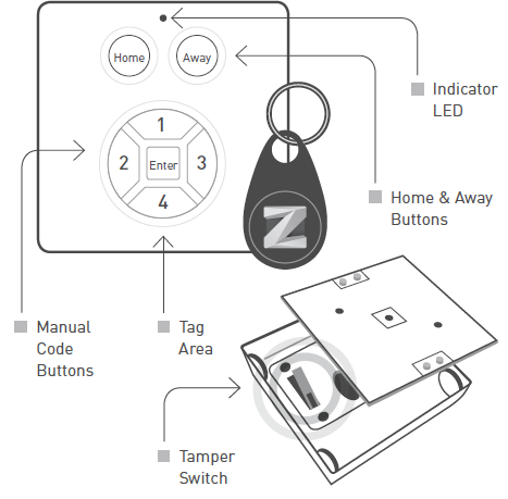
LED Indicator
The indicator gives various statuses of the device as follows:
CONTROL
There are two types of Access Control with User Codes:
There are some situations:
2 | IN CASE A KNOWN MANUAL CODE OR TAG IS PRESENTED. This means, this code was previously SET using the USER_CODE_ SET command. Then the Mini Keypad RFiD/Z-Wave will respond with a ALARM_REPORT_V2 with Type 6 and Event 0x05 or 0x06. When the user presses Home, event 0x06 (Keypad Unlock) will be used. When the user presses Away, event 0x05 (Keypad Lock) will be used.
AFTER THIS THERE ARE TWO POSSIBILITIES:
| Reset to factory default | XXXResetDescription |
| Inclusion | Press and hold the tamper for 1 seconds and release to start the inclusion process (indication mode: Ready for learn mode). |
| Exclusion | Press and hold the tamper for 1 seconds and release to start the exclusion process (indication mode: Ready for learn mode). |
| NIF | XXXNIF |
| Wakeup | The always awake mode is used to request different values from the device e.g. version and manufacturer specific.
NOTE: in always awake mode the batteries will be drain very fast, we do not recommend to use this mode for a longer period. Always awake mode should only be used in order to configure the device. NOTE: it is not possible to use the buttons of the Mini Keypad RFiD/ZWave while it is operating in always awake mode. |
| Protection | XXXProtection |
| FirmwareUpdate | XXXFirmwareUpdate |
| SetAssociation | XXXSetAssociation |
Association Groups:
| Group Number | Maximum Nodes | Description |
|---|---|---|
| 1 | 5 | Lifeline |
Configuration Parameters
Parameter 1: Factory settingf
Size: 1 Byte, Default Value: 0
| Setting | Description |
|---|---|
| 85 | Configuration settings of the device are altered. The device will report this even if the configuration parameters are changed back to the default value. |
| 170 | Configuration of the device is untouched. Note that this value will not change to 0x55 upon modifying the wake up interval and that re-setting the value to 0xAA will always reset the wake up interval. |
| 255 | set default |
Parameter 2: Feedback time
To configure the time the beep is automatically turned off in seconds. Size: 1 Byte, Default Value: 16
| Setting | Description |
|---|---|
| 0 - 255 | seconds |
Parameter 3: Feedback timeout
To configure the timeout to wait for a WAKEUP_NO_MORE_INFORMATION before the error beep is automatically sound. The error beeps are fixed 8 beeps shortly after each other. Size: 1 Byte, Default Value: 0
| Setting | Description |
|---|---|
| 0 - 255 | seconds |
Parameter 4: Feedback beeps per second
To configure the number of beeps per second. Every beep is fixed about 10ms. Size: 1 Byte, Default Value: 2
| Setting | Description |
|---|---|
| 1 - 7 | nr of beeps per second |
Parameter 5: The mode
To configure the operating mode. Size: 1 Byte, Default Value: 1
| Setting | Description |
|---|---|
| 1 | Normal operating mode. |
| 3 | Z-Wave chip is always on to request e.g. version or manufacturer id. If any mode other then 3, that value will be reported after a get but will be handled in SW as mode 1. |
Technical Data
| Dimensions | 62x62x17 mm |
| Weight | 45 gr |
| Hardware Platform | ZM3102 |
| EAN | 3858890730579 |
| IP Class | IP 20 |
| Battery Type | 2 * AA 1,5V |
| Device Type | Lock |
| Firmware Version | 00.1c |
| Z-Wave Version | 03.43 |
| Z-Wave Product Id | 0x0097.0x6131.0x4501 |
| Frequency | Europe - 868,4 Mhz |
| Maximum transmission power | 5 mW |