Z-Wave.Me
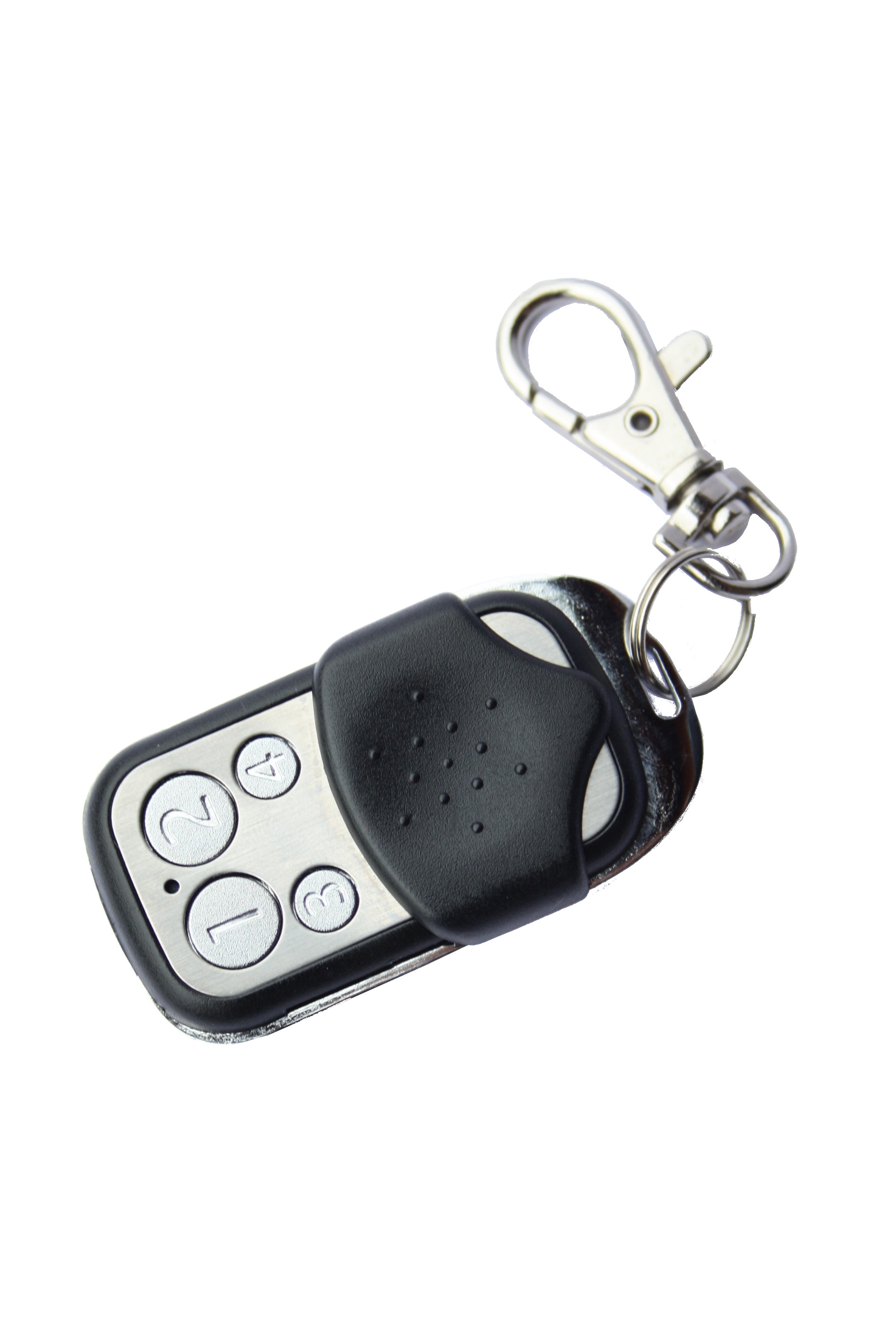
Secure Key Chain Controller
SKU: ZMEEKFOBC


Quickstart
This is a
Important safety information
Please read this manual carefully. Failure to follow the recommendations in this manual may be dangerous or may violate the law. The manufacturer, importer, distributor and seller shall not be liable for any loss or damage resulting from failure to comply with the instructions in this manual or any other material. Use this equipment only for its intended purpose. Follow the disposal instructions. Do not dispose of electronic equipment or batteries in a fire or near open heat sources.What is Z-Wave?
Z-Wave is the international wireless protocol for communication in the Smart Home. This device is suited for use in the region mentioned in the Quickstart section.
Z-Wave ensures a reliable communication by reconfirming every message (two-way communication) and every mains powered node can act as a repeater for other nodes (meshed network) in case the receiver is not in direct wireless range of the transmitter.
This device and every other certified Z-Wave device can be used together with any other certified Z-Wave device regardless of brand and origin as long as both are suited for the same frequency range.
If a device supports secure communication it will communicate with other devices secure as long as this device provides the same or a higher level of security. Otherwise it will automatically turn into a lower level of security to maintain backward compatibility.
For more information about Z-Wave technology, devices, white papers etc. please refer to www.z-wave.info.
Product Description
The Secure Key Fob Controller is a 4 button Z-Wave device capable to act both as primary or secondary controller. The four buttons can control other Z-Wave devices such as switches, dimmer and even door locks directly. Various options - configurable by Z-Wave configuration commands - define the actions and the commands used for this control. It is possible to use two sets of buttons (one of on/open/up and one for off/closed/down) or 4 single buttons to control 4 different groups of devices.
The controller also allows triggering scenes in a central controller. Again different modes can be configured to adapt to the various implementations of scenes in different central controllers in the market.
Control options also include special modes like "all on/off" or always controlling the Z-Wave device in proximity to the fob. The device supports secure communication when included with enhanced security option and when communicating to a device also supporting enhanced security option. Otherwise the device will automatically turn into normal communication. to maintain backward compatibility.
Prepare for Installation / Reset
Please read the user manual before installing the product.
In order to include (add) a Z-Wave device to a network it must be in factory default state. Please make sure to reset the device into factory default. You can do this by performing an Exclusion operation as described below in the manual. Every Z-Wave controller is able to perform this operation however it is recommended to use the primary controller of the previous network to make sure the very device is excluded properly from this network.
Reset to factory default
This device also allows to be reset without any involvement of a Z-Wave controller. This procedure should only be used when the primary controller is inoperable.
Enter management mode by push all four buttons together for one second - green led blinks slowly), then hit button 3 followed by keeping button 4 pushed down for 10 seconds. The first five seconds the green LED still blinks followed by a long red, shot green sequence. Once LEDs go off, reset was executed. Please use this procedure only if the device is secondary controller and the primary controller is missing or otherwise inoperable.
Inclusion/Exclusion
On factory default the device does not belong to any Z-Wave network. The device needs to be added to an existing wireless network to communicate with the devices of this network. This process is called Inclusion.
Devices can also be removed from a network. This process is called Exclusion. Both processes are initiated by the primary controller of the Z-Wave network. This controller is turned into exclusion respective inclusion mode. Inclusion and Exclusion is then performed doing a special manual action right on the device.
Inclusion
When in factory default push Button 3 (secure) or Button 4 (normal) for one second to enter inclusion mode. The inclusion mode is indicated by a blinking green LED. From second device on you need to enter management mode push all four buttons together for one second - green led blinks slowly), hit button 3 ( enter primary controller functions - green led blinks faster) and then button 1 (secure) or button 2 (normal).Exclusion
Enter management mode by push all four buttons together for one second - green led blinks slowly), hit button 3 ( enter primary controller functions - green led blinks faster) and then button 3 again.Communication to a Sleeping device (Wakeup)
This device is battery operated and turned into deep sleep state most of the time to save battery life time. Communication with the device is limited. In order to communicate with the device, a static controller C is needed in the network. This controller will maintain a mailbox for the battery operated devices and store commands that can not be received during deep sleep state. Without such a controller, communication may become impossible and/or the battery life time is significantly decreased.
This device will wakeup regularly and announce the wakeup state by sending out a so called Wakeup Notification. The controller can then empty the mailbox. Therefore, the device needs to be configured with the desired wakeup interval and the node ID of the controller. If the device was included by a static controller this controller will usually perform all necessary configurations. The wakeup interval is a tradeoff between maximal battery life time and the desired responses of the device. To wakeup the device please perform the following action: Enter management mode by push all four buttons together for one second - green led blinks slowly), then hit button 2 .
Quick trouble shooting
Here are a few hints for network installation if things dont work as expected.
- Make sure a device is in factory reset state before including. In doubt exclude before include.
- If inclusion still fails, check if both devices use the same frequency.
- Remove all dead devices from associations. Otherwise you will see severe delays.
- Never use sleeping battery devices without a central controller.
- Dont poll FLIRS devices.
- Make sure to have enough mains powered device to benefit from the meshing
Association - one device controls an other device
Z-Wave devices control other Z-Wave devices. The relationship between one device controlling another device is called association. In order to control a different device, the controlling device needs to maintain a list of devices that will receive controlling commands. These lists are called association groups and they are always related to certain events (e.g. button pressed, sensor triggers, ...). In case the event happens all devices stored in the respective association group will receive the same wireless command wireless command, typically a 'Basic Set' Command.
Association Groups:
| Group Number | Maximum Nodes | Description |
|---|---|---|
| 1 | 10 | Z-Wave Plus Lifeline |
| 2 | 10 | Control Group A, controlled by button 1 or single clicks of buttons 1 and 3 |
| 3 | 10 | Control Group B, controlled by button 2 or single clicks of buttons 2 and 4 |
| 4 | 10 | Control Group C, controlled by button 3 or double clicks of buttons 1 and 3 |
| 5 | 10 | Control Group D, controlled by button 4 or double clicks of buttons 2 and 4 |
Configuration Parameters
Z-Wave products are supposed to work out of the box after inclusion, however certain configuration can adapt the function better to user needs or unlock further enhanced features.
IMPORTANT: Controllers may only allow configuring signed values. In order to set values in the range 128 ... 255 the value sent in the application shall be the desired value minus 256. For example: To set a parameter to 200 it may be needed to set a value of 200 minus 256 = minus 56. In case of a two byte value the same logic applies: Values greater than 32768 may needed to be given as negative values too.
Parameter 1: Button 1 and 3 pair mode
In separate mode button 1 works with group A, button 3 with groups C. Click is On, Hold is dimming Up, Double click is Off, Click-Hold is dimming Down. In pair button 1/3 are Up/Down correspondingly. Click is On/Off, Hold is dimming Up/Down. Single clicks works with group A, double click with group C. Size: 1 Byte, Default Value: 1
| Setting | Description |
|---|---|
| 2 | In pair with double clicks |
| 0 | seperately |
| 1 | In pair without double clicks |
Parameter 11: Command to Control Group A
This parameter defines the command to be sent to devices of control group A when the related button is pressed Size: 1 Byte, Default Value: 8
| Setting | Description |
|---|---|
| 5 | Send Preconfigured Scenes |
| 7 | Control DoorLock |
| 8 | Central Scene to Gateway |
| 0 | Disabled |
| 1 | Switch On/Off and Dim (send Basic Set and Switch Multilevel) |
| 2 | Switch On/Off only (send Basic Set) |
| 3 | Switch All |
| 4 | Send Scenes |
Parameter 12: Command to Control Group B
This parameter defines the command to be sent to devices of control group B when the related button is pressed Size: 1 Byte, Default Value: 8
| Setting | Description |
|---|---|
| 4 | Send Scenes |
| 3 | Switch All |
| 5 | Send Preconfigured Scenes |
| 7 | Control DoorLock |
| 8 | Central Scene to Gateway |
| 0 | Disabled |
| 1 | Switch On/Off and Dim (send Basic Set and Switch Multilevel) |
| 2 | Switch On/Off only (send Basic Set) |
Parameter 13: Command to Control Group C
This parameter defines the command to be sent to devices of control group C when the related button is pressed Size: 1 Byte, Default Value: 8
| Setting | Description |
|---|---|
| 0 | Disabled |
| 1 | Switch On/Off and Dim (send Basic Set and Switch Multilevel) |
| 2 | Switch On/Off only (send Basic Set) |
| 3 | Switch All |
| 4 | Send Scenes |
| 5 | Send Preconfigured Scenes |
| 7 | Control DoorLock |
| 8 | Central Scene to Gateway |
Parameter 14: Command to Control Group D
This parameter defines the command to be sent to devices of control group D when the related button is pressed Size: 1 Byte, Default Value: 8
| Setting | Description |
|---|---|
| 1 | Switch On/Off and Dim (send Basic Set and Switch Multilevel) |
| 0 | Disabled |
| 2 | Switch On/Off only (send Basic Set) |
| 3 | Switch All |
| 4 | Send Scenes |
| 5 | Send Preconfigured Scenes |
| 7 | Control DoorLock |
| 8 | Central Scene to Gateway |
Parameter 2: Button 2 and 4 pair mode
In separate mode button 2 works with control group B, button 4 with control group D. Click is On, Hold is dimming Up, Double click is Off, Click-Hold is dimming Down. In pair button B/D are Up/Down correspondingly. Click is On/Off, Hold is dimming Up/Down. Single clicks works with group B, double click with group D. Size: 1 Byte, Default Value: 1
| Setting | Description |
|---|---|
| 2 | In pair with double clicks |
| 1 | In pair without double clicks |
| 0 | seperately |
Parameter 21: Send the following Switch All commands
Size: 1 Byte, Default Value: 1
| Setting | Description |
|---|---|
| 1 | Switch off only |
| 2 | Switch on only |
| 255 | Switch all on and off |
Parameter 22: Invert buttons
Size: 1 Byte, Default Value: 0
| Setting | Description |
|---|---|
| 1 | Yes |
| 0 | No |
Parameter 25: Blocks wakeup even when wakeup interval is set
Size: 1 Byte, Default Value: 1
| Setting | Description |
|---|---|
| 0 | Wakeup is blocked |
| 1 | Wakeup is not blocked |
Parameter 30: Send unsolicited Battery Report on Wake Up
Size: 1 Byte, Default Value: 0
| Setting | Description |
|---|---|
| 0 | No |
| 1 | To same node as wake up notification |
| 2 | Broadcast |
Technical Data
| Dimensions | 30x55x15 mm |
| Weight | 32 gr |
| Hardware Platform | ZM5202 |
| EAN | 0019962007002 |
| Device Type | Remote Control - Simple |
| Network Operation | Portable Controller |
| Z-Wave Version | 6.51.03 |
| Certification ID | ZC10-15050016 |
| Z-Wave Product Id | 0x0115.0x0100.0x0103 |
| Frequency | Europe - 868,4 Mhz |
| Maximum transmission power | 5 mW |
Supported Command Classes
- Association
- Association Group Information
- Battery
- Central Scene
- Configuration
- Device Reset Locally
- Manufacturer Specific
- Multi Channel Association
- Multi Command
- Powerlevel
- Scene Controller Conf
- Security
- Version
- Wake Up
- Zwaveplus Info
Controlled Command Classes
- Basic
- Central Scene
- Door Lock
- Multi Channel
- Multi Command
- Security
- Switch Multilevel
- Wake Up
Explanation of Z-Wave specific terms
- Controller — is a Z-Wave device with capabilities to manage the network. Controllers are typically Gateways,Remote Controls or battery operated wall controllers.
- Slave — is a Z-Wave device without capabilities to manage the network. Slaves can be sensors, actuators and even remote controls.
- Primary Controller — is the central organizer of the network. It must be a controller. There can be only one primary controller in a Z-Wave network.
- Inclusion — is the process of adding new Z-Wave devices into a network.
- Exclusion — is the process of removing Z-Wave devices from the network.
- Association — is a control relationship between a controlling device and a controlled device.
- Wakeup Notification — is a special wireless message issued by a Z-Wave device to announces that is able to communicate.
- Node Information Frame — is a special wireless message issued by a Z-Wave device to announce its capabilities and functions.