Z-Wave.Me
Z-Wave.Me Wall Controller ZP (secondary controller)
SKU: ZMEEWALLCZP

Quickstart
This is a
Important safety information
Please read this manual carefully. Failure to follow the recommendations in this manual may be dangerous or may violate the law. The manufacturer, importer, distributor and seller shall not be liable for any loss or damage resulting from failure to comply with the instructions in this manual or any other material. Use this equipment only for its intended purpose. Follow the disposal instructions. Do not dispose of electronic equipment or batteries in a fire or near open heat sources.Product Description
The Z-Wave.Me Wall Controller is a Z-Wave device that can both control other Z-Wave devices and activate predefined scenes in an IP gateway. Although it is controlling other devices, the Wall Controller cannot act as Z-Wave network controller (primary or secondary) and will always need a Z-Wave network controller to be included into a Z-Wave network. The device can be used in different modes that are selected by configuration parameters:
- Control of groups of other Z-Wave devices using "ON", "OFF" and Dim commands.
- Activation of predefined scenes in Gateways or other Z-Wave devices.
The wall controller must be completed by a mounting frame, the wall switch frame and a rocker. They are not scope of delivery of this device.
This device support secure communication when included by a controller that also supports secure communication. The device will then send all commands as secure commands unless the receiving device can not accept them. Then the command is send the normal way automatically.
The device will be completed with different designs of wall frame and rockers.
For example:
- Berker (S.1, B.1, B.3, B.7 Glass),
- GIRA (System 55, Standard 55, E2, E22, Event, Esprit),
- Merten (1-M, Atelier-M, M-Smart, M-Arc, M-Star, M-Plan),
- Schneider Electric Exxact,
- Jung (A 500, AS 500, A plus, A creation)
- Kopp HK07
Installation
The device can be mounted on every dry and flat surface using either screws or double side adhesive. First the mounting base is fixed on the wall. Next step the switch frame is placed on the 2 frame and the electronic insert is used to fix the frame to the mounting base as shown on the image. Finally the switching paddle(s) are mounted on the electronic base.
For battery change, the switching paddle(s) need to be removed. The CR battery can be replaced by pushing the little nipple above the battery. The old battery will slide out and the new battery is inserted until the nipple will hold it again.
The device can be operated in two different modes:
- Operation Mode: This is the mode where the device is controlling other Z-Wave devices or is activating scenes.
- Management Mode: The device is turned into the management mode by pushing all four buttons for 5 sec. A blinking green LED indicates the management mode. In the management mode the buttons of the device have different functions. If no further action is performed, the device will turn back to the normal mode after 10 sec. Any management action terminates the management mode as well.
In management mode the following actions can be performed:
- Button 1 - Re-Inclusion/Exclusion: Every re-inclusion or exclusion attempt is confirmed by hitting this button. Any button press stops the mode as well.
- Button 2 - Send Node Information Frame and Wake up Notification. (see explanation below)
- Button 3 - Factory Default Reset. After clicking on button 3 keep button 4 pushed for >4 seconds
- Button 4 - Enter into Association mode to assign target devices to one of the four association. Refer to the manuals section about association for more information how to set and unset association groups.
Product Usage
Depending on the button mode and operating modes configured using the configuration parameters the key fob can be used in different ways.
Button modes:
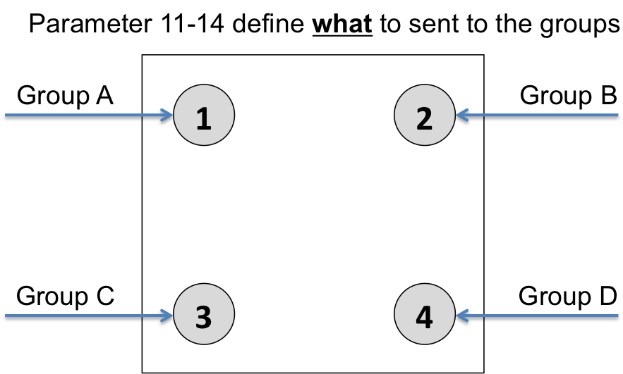
4 Groups are controlled with single button (parameter 1/2 = 0) The four buttons 1-4 control one single control group each: 1->A, 2->B, 3->C, 4->D. Single click turns devices in the control group on, double click turns them off. Click and hold can be used for dimming.
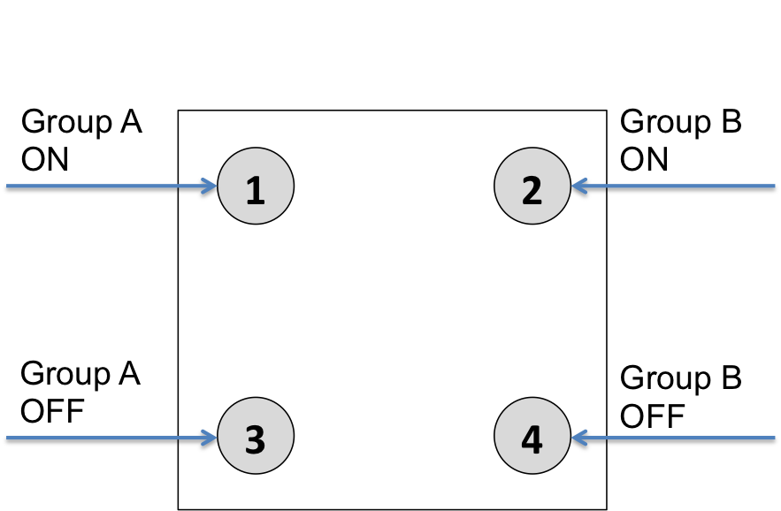
2 Groups are controlled with two buttons (parameter 1/2 = 1) The buttons 1 and 3 control the control group A (button on turns on, buttons turns off), the buttons 2 and 4 control the control group B (button on turns on, buttons turns off). In case dimmers are controlled, holding down the larger button will dim up, holding down the smaller button will dim down the load. Releasing the button will stop the dimming function.
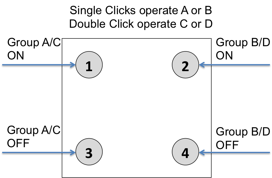
4 Groups are controlled with two buttons and double click (parameter 1/2 = 2) This mode enhances the previous mode and allows to control two further control groups C and D using double clicks.
Operating modes:
The devices supports 8 different operating modes - this means the kind of command sent out when pushing a button. Operating modes either directly control other devices or they issue various scene activation commands to a central controller. Operating modes for direct device control are:- Direct Control of associated devices with On/Off/Dim commands (parameter 11...14 = 1). Devices are controlled using Basic Set On/Off commands and SwitchMultilevel Dim Start/Stop. This mode implements communication pattern 7.
- Direct Control of associated devices with only On/Off commands (parameter 11...14 = 2). Devices are controlled using only Basic Set On/Off commands. On dimming Up event On is sent, on dimming Down Off is sent. This mode also implements communication pattern 7.
- Switch All commands (parameter 11...14 = 3) In this mode a all neighbouring devices will receive SwitchAll Set On/Off command and interpret it according to their membership in SwitchAll groups. This mode implements communication pattern 7.
- Door Lock Control (parameter 11...14 = 7) This modes allows direct control (open/close) of electronic door locks using secure communication. The mode implements communication pattern 7.
- Direct Activation of preconfigured scenes (parameter 11...14 = 5) Associated devices in an association group are controlled by individual commands defines by Z-Wave command class ?Scene Controller Configuration?. This mode enhances mode Direct Control of associated devices with On/Off/Dim commands and implements communication patterns 6 and 7. Please turn the button mode to "seperate" to allows different scene id on every button.
- Scene Activation in IP Gateway (parameter 11...14 = 4) If configured correctly the buttons can trigger a scene in a gateway. The scene number triggered is a combination of the group number and the action performed on the button and has always two digits. The group number defines the upper digit of the scene number, the action the lower digit. The following actions are possible:
- 1 = On
- 2 = Off
- 3 = Dim Up Start
- 4 = Dim Down Start
- 5 = Dim Up Stop
- 6 = Dim Down Stop
Example: Clicking/double clicking the button will issue scene triggers, scene 11 (button 1 click, event on), scene 12 (button double click 1, event off, single button control is used in this example)
- Activation of Central Scenes (parameter 11...14 = 8,Default) Z-Wave Plus introduces a new process for scene activation - the central scene control. Pushing a button and releasing a button sends a certain command to the central controller using the lifeline association group. This allows to react both on button push and button release. This mode implements communication patterns 6 but requires a central gateway supporting Z-Wav Plus.
| Reset to factory default | The device can be set back to factory defaults without performing an exclusion process. Please executes the following steps: (1) Turn the device into Management Mode, (2) click on Button 3, (3) keep button 4 pushed for 4 seconds. |
| Inclusion | XXXInclusionDescription |
| Exclusion | XXXExclusionDescription |
| NIF | Pressing Button 2 in management mode will issue a Node Information Frame. |
| Wakeup | XXXWakeupDescription |
| Protection | XXXProtection |
| FirmwareUpdate | XXXFirmwareUpdate |
| SetAssociation | To control a Z-Wave device from the Wall Controller the node ID of this devices needs to be assigned to one of the four association groups. This is a three-step process:
|
Association Groups:
| Group Number | Maximum Nodes | Description |
|---|---|---|
| 1 | 10 | Lifeline |
| 2 | 10 | Control Group A |
| 3 | 10 | Control Group B |
| 4 | 10 | Control Group C |
| 5 | 10 | Control Group D |
Configuration Parameters
Parameter 1: Button 1 and 3 pair mode
In separate mode button 1 works with Group A, button 3 with Group C. Click is ON, Hold is dimming UP, Double click is OFF, Click-Hold is dimming DOWN. In pair button 1/3 are UP/DOWN correspondingly. Click is ON/OFF, Hold is dimming UP/DOWN. Single clicks works with Group A, double click with Group C. Size: 1 Byte, Default Value: 1
| Setting | Description |
|---|---|
| 0 | Separately |
| 1 | In pair without double clicks |
| 2 | In pair with double clicks |
Parameter 2: Button 2 and 4 pair mode
In separate mode button 2 works with control group B, button 4 with control group D. Click is ON, Hold is dimming UP, Double click is OFF, Click-Hold is dimming DOWN. In pair button B/D are UP/DOWN correspondingly. Click is ON/OFF, Hold is dimming UP/DOWN. Single clicks works with Group B, double click with Group D. Size: 1 Byte, Default Value: 1
| Setting | Description |
|---|---|
| 0 | Separately |
| 1 | In pair without double clicks |
| 2 | In pair with double clicks |
Parameter 11: Command to control Group A
This parameter defines the command to be sent to devices of control group A when the related button is pressed. Size: 1 Byte, Default Value: 8
| Setting | Description |
|---|---|
| 0 | Disable |
| 1 | Switch on/off and Dim (send Basic Set and Switch Multilevel) |
| 2 | Switch on/off only (send Basic Set) |
| 3 | Switch all |
| 4 | Send scenes |
| 5 | Send preconfigured scenes |
| 6 | Control devices in proximity |
| 7 | Control door lock |
| 8 | Central scene to gateway (default) |
Parameter 12: Command to control Group B
This parameter defines the command to be sent to devices of control group B when the related button is pressed. Size: 1 Byte, Default Value: 8
| Setting | Description |
|---|---|
| 0 | Disable |
| 1 | Switch on/off and Dim (send Basic Set and Switch Multilevel) |
| 2 | Switch on/off only (send Basic Set) |
| 3 | Switch all |
| 4 | Send scenes |
| 5 | Send preconfigured scenes |
| 6 | Control devices in proximity |
| 7 | Control door lock |
| 8 | Central scene to gateway (default) |
Parameter 13: Command to control Group C
This parameter defines the command to be sent to devices of control group C when the related button is pressed. Size: 1 Byte, Default Value: 8
| Setting | Description |
|---|---|
| 0 | Disable |
| 1 | Switch on/off and Dim (send Basic Set and Switch Multilevel) |
| 2 | Switch on/off only (send Basic Set) |
| 3 | Switch all |
| 4 | Send scenes |
| 5 | Send preconfigured scenes |
| 6 | Send preconfigured scenes |
| 7 | Control door lock |
| 8 | Central scene to gateway |
Parameter 14: Command to control Group D
This parameter defines the command to be sent to devices of control group D when the related button is pressed. Size: 1 Byte, Default Value: 8
| Setting | Description |
|---|---|
| 0 | Disable |
| 1 | Switch on/off and Dim (send Basic Set and Switch Multilevel) |
| 2 | Switch on/off only (send Basic Set) |
| 3 | Switch all |
| 4 | Send scenes |
| 5 | Send preconfigured scenes |
| 6 | Control devices in proximity |
| 7 | Control door lock |
| 8 | Central scene to gateway (default) |
Parameter 21: Send the following switch all commands
Size: 1 Byte, Default Value: 1
| Setting | Description |
|---|---|
| 1 | Switch off only |
| 2 | Switch on only |
| 255 | Switch all on and off |
Parameter 22: Invert buttons
Size: 1 Byte, Default Value: 0
| Setting | Description |
|---|---|
| 0 | No |
| 1 | Yes |
Parameter 25: Blocks wake up even when Wake Up Interval is set
If the KFOB wakes up and there is no controller nearby, several unsuccessful communication attempts will drain battery. Size: 1 Byte, Default Value: 0
| Setting | Description |
|---|---|
| 0 | Wake up is blocked |
| 1 | Wake up is possible if configured accordingly |
Parameter 30: Send unsolicited battery report on Wake Up
Size: 1 Byte, Default Value: 1
| Setting | Description |
|---|---|
| 0 | No |
| 1 | To same node as Wake Up Notification |
| 2 | Broadcast to neighbors |
Technical Data
| Dimensions | 70 x 70 x 13 mm |
| Weight | 30 gr |
| Hardware Platform | ZM5202 |
| EAN | 4251295700847 |
| IP Class | IP 20 |
| Voltage | 3V |
| Battery Type | 1 * CR2032 |
| Frequency | Europe - 868,4 Mhz |
| Maximum transmission power | 5 mW |