Z-Wave.Me
Z-Wave Remote Control
SKU: ZME_RC2
Quickstart
This is a
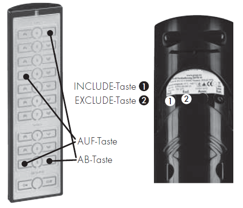
Push the "Include" button behind the slider on the back side 3 times includes the device into an existing the Z-Wave network. The device can not act as primary network controller.
Important safety information
Please read this manual carefully. Failure to follow the recommendations in this manual may be dangerous or may violate the law. The manufacturer, importer, distributor and seller shall not be liable for any loss or damage resulting from failure to comply with the instructions in this manual or any other material. Use this equipment only for its intended purpose. Follow the disposal instructions. Do not dispose of electronic equipment or batteries in a fire or near open heat sources.What is Z-Wave?
Z-Wave is the international wireless protocol for communication in the Smart Home. This device is suited for use in the region mentioned in the Quickstart section.
Z-Wave ensures a reliable communication by reconfirming every message (two-way communication) and every mains powered node can act as a repeater for other nodes (meshed network) in case the receiver is not in direct wireless range of the transmitter.
This device and every other certified Z-Wave device can be used together with any other certified Z-Wave device regardless of brand and origin as long as both are suited for the same frequency range.
If a device supports secure communication it will communicate with other devices secure as long as this device provides the same or a higher level of security. Otherwise it will automatically turn into a lower level of security to maintain backward compatibility.
For more information about Z-Wave technology, devices, white papers etc. please refer to www.z-wave.info.
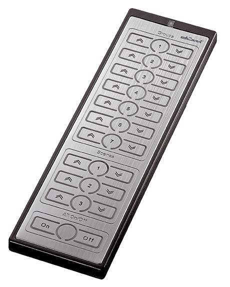
Product Description
The Z-Wave.Me Remote controls Z-Wave actuators such as dimmers, switches, thermostats or motor controls for blinds or jalousies and it can activate scenes in central gateways or any other Z-Wave devices. Devices can be turned on and off but dimmers and motor controls can also be turned into a desired dimming level to motor position by keeping a button pushed and releasing it. Although it is controlling other devices, the device can not act as Z-Wave network controller (primary or secondary) and will always need a Z-Wave network controller to be included into a Z-Wave network. The device can be used in different modes that are selected by configuration parameters 11-21:
- Direct control of associated devices
- Control of all devices in the Z-Wave network
- Simple and enhanced scene activation
10 pair of buttons - illuminated by blue light when operated - allow to control up to 10 control groups (either association groups or scenes)
Prepare for Installation / Reset
Please read the user manual before installing the product.
In order to include (add) a Z-Wave device to a network it must be in factory default state. Please make sure to reset the device into factory default. You can do this by performing an Exclusion operation as described below in the manual. Every Z-Wave controller is able to perform this operation however it is recommended to use the primary controller of the previous network to make sure the very device is excluded properly from this network.
Safety Warning for Batteries
The product contains batteries. Please remove the batteries when the device is not used. Do not mix batteries of different charging level or different brands.
Inclusion/Exclusion
On factory default the device does not belong to any Z-Wave network. The device needs to be added to an existing wireless network to communicate with the devices of this network. This process is called Inclusion.
Devices can also be removed from a network. This process is called Exclusion. Both processes are initiated by the primary controller of the Z-Wave network. This controller is turned into exclusion respective inclusion mode. Inclusion and Exclusion is then performed doing a special manual action right on the device.
Inclusion
For including the remote control into an existing the Z-Wave network do the following steps:
- Bring your primary controller into inclusion mode.
- For Inclusion press the "Inclusion" button 3 times. The LED will flash green for a moment for confirmation.
Exclusion
For excluding the remote control into an existing the Z-Wave network do the following steps:
- Bring your primary controller into exclusion mode.
- For Exclusion press the "Exclusion" button for 5 secs. The LED will flash green for a moment for confirmation.
Product Usage
This Remote Control has 10 different button groups to control 10 different devices or groups of devices.
Operating modes for direct device control:
The devices supports 8 different operating modes for these groups - this means the kind of command sent out when pushing a button. Operating modes either directly control other devices or they issue various scene activation commands to a central controller. Operating modes for direct device control are:
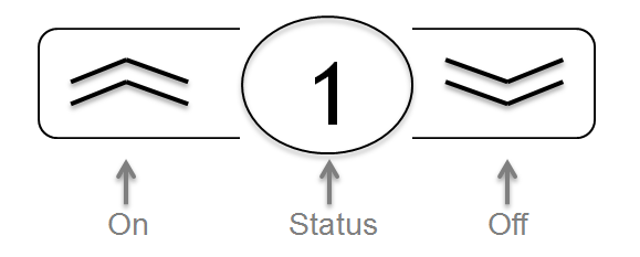
- Direct Control of associated devices with On/Off/Dim commands (parameter 11...21 = 1). Devices are controlled using Basic Set On/Off commands and SwitchMultilevel Dim Start/Stop. This mode implements communication pattern 7. Each button of the button group has different functions:
- ,On" - short click: turn on device(s)
- ,On" - pushed: dim up light or wind up jalousie until button is released
- ,Off" - short click: turn off device(s)
- ,Off" - pushed: dim down light or wind down jalousie until button is released
- Status: Call the status of the device controlled. Blue LED indicated "on", red LED indicates "off". A blinking LED indicated that different devices controlled by this button group have different switching states.
- Direct Control of associated devices with only On/Off commands (parameter 11...21 = 2). Devices are controlled using only Basic Set On/Off commands. On dimming Up event On is sent, on dimming Down Off is sent. This mode also implements communication pattern 7.
- Switch All commands (parameter 11...21 = 3) In this mode a all neighbouring devices will receive SwitchAll Set On/Off command and interpret it according to their membership in SwitchAll groups. This mode implements communication pattern 7.
- Direct Activation of preconfigured scenes (parameter 11...21 = 5) This mode causes the button of the groups to send out the number of the group (1..10) as scene activation command and implements communication patterns 6 and 7.
- Scene Activation in IP Gateway (parameter 11...21 = 4) If configured correctly the buttons can trigger a scene in a gateway. The scene number triggered is a combination of the group number and the action performed on the button and has always two digits. The group number defines the upper digit of the scene number, the action the lower digit. The following actions are possible:
- 1 = On
- 2 = Off
- 3 = Dim Up Start
- 4 = Dim Down Start
- 5 = Dim Up Stop
- 6 = Dim Down Stop
Example: Clicking/double clicking the button will issue scene triggers, scene 11 (button 1 click, event on), scene 12 (button double click 1, event off, single button control is used in this example)
Node Information Frame
The Node Information Frame (NIF) is the business card of a Z-Wave device. It contains information about the device type and the technical capabilities. The inclusion and exclusion of the device is confirmed by sending out a Node Information Frame. Beside this it may be needed for certain network operations to send out a Node Information Frame. To issue a NIF execute the following action:
Pressing the
Communication to a Sleeping device (Wakeup)
This device is battery operated and turned into deep sleep state most of the time to save battery life time. Communication with the device is limited. In order to communicate with the device, a static controller C is needed in the network. This controller will maintain a mailbox for the battery operated devices and store commands that can not be received during deep sleep state. Without such a controller, communication may become impossible and/or the battery life time is significantly decreased.
This device will wakeup regularly and announce the wakeup state by sending out a so called Wakeup Notification. The controller can then empty the mailbox. Therefore, the device needs to be configured with the desired wakeup interval and the node ID of the controller. If the device was included by a static controller this controller will usually perform all necessary configurations. The wakeup interval is a tradeoff between maximal battery life time and the desired responses of the device. To wakeup the device please perform the following action:
Pressing the "INCL." button for three times will wake up the device.
Quick trouble shooting
Here are a few hints for network installation if things dont work as expected.
- Make sure a device is in factory reset state before including. In doubt exclude before include.
- If inclusion still fails, check if both devices use the same frequency.
- Remove all dead devices from associations. Otherwise you will see severe delays.
- Never use sleeping battery devices without a central controller.
- Dont poll FLIRS devices.
- Make sure to have enough mains powered device to benefit from the meshing
Association - one device controls an other device
Z-Wave devices control other Z-Wave devices. The relationship between one device controlling another device is called association. In order to control a different device, the controlling device needs to maintain a list of devices that will receive controlling commands. These lists are called association groups and they are always related to certain events (e.g. button pressed, sensor triggers, ...). In case the event happens all devices stored in the respective association group will receive the same wireless command wireless command, typically a 'Basic Set' Command.
Association Groups:
| Group Number | Maximum Nodes | Description |
|---|---|---|
| 1 | 5 | Lifeline. Send to controller battery level and WakeUp Notification |
| 2 | 5 | The buttons of group u21161 |
| 3 | 5 | The buttons of group u21162 |
| 4 | 5 | The buttons of group u21163 |
| 5 | 5 | The buttons of group u21164 |
| 6 | 5 | The buttons of group u21165 |
| 7 | 5 | The buttons of group u21166 |
| 8 | 5 | The buttons of group u21167 |
| 9 | 5 | The buttons of scene u21161 |
| 10 | 5 | The buttons of scene u21162 |
| 11 | 5 | The buttons of scene u21163 |
| 12 | 5 | The buttons of All On/Off |
Configuration Parameters
Z-Wave products are supposed to work out of the box after inclusion, however certain configuration can adapt the function better to user needs or unlock further enhanced features.
IMPORTANT: Controllers may only allow configuring signed values. In order to set values in the range 128 ... 255 the value sent in the application shall be the desired value minus 256. For example: To set a parameter to 200 it may be needed to set a value of 200 minus 256 = minus 56. In case of a two byte value the same logic applies: Values greater than 32768 may needed to be given as negative values too.
Parameter 10: Command to Control Group u21161 (association group 2)
This parameter defines the command to be sent to devices of control group u21161 when the related button is pressed (association group 2) Size: 1 Byte, Default Value: 01
| Setting | Description |
|---|---|
| 00 | Disabled |
| 01 | Switch On/Off and Dim (send Basic Set and Switch Multilevel) |
| 02 | Switch On/Off only (send Basic Set) |
| 03 | Switch All |
| 04 | Send Scenes |
| 05 | Send Preconfigured Scenes |
Parameter 11: Command to Control Group u21162 (association group 3)
This parameter defines the command to be sent to devices of control group u21162 when the related button is pressed (association group 3) Size: 1 Byte, Default Value: 01
| Setting | Description |
|---|---|
| 00 | Disabled |
| 01 | Switch On/Off and Dim (send Basic Set and Switch Multilevel) |
| 02 | Switch On/Off only (send Basic Set) |
| 03 | Switch All |
| 04 | Send Scenes |
| 05 | Send Preconfigured Scenes |
Parameter 12: Command to Control Group u21163 (association group 4)
This parameter defines the command to be sent to devices of control group u21163 when the related button is pressed (association group 4) Size: 1 Byte, Default Value: 01
| Setting | Description |
|---|---|
| 00 | Disabled |
| 01 | Switch On/Off and Dim (send Basic Set and Switch Multilevel) |
| 02 | Switch On/Off only (send Basic Set) |
| 03 | Switch All |
| 04 | Send Scenes |
| 05 | Send Preconfigured Scenes |
Parameter 13: Command to Control Group u21164 (association group 5)
This parameter defines the command to be sent to devices of control group u21164 when the related button is pressed (association group 5) Size: 1 Byte, Default Value: 01
| Setting | Description |
|---|---|
| 00 | Disabled |
| 01 | Switch On/Off and Dim (send Basic Set and Switch Multilevel) |
| 02 | Switch On/Off only (send Basic Set) |
| 03 | Switch All |
| 04 | Send Scenes |
| 05 | Send Preconfigured Scenes |
Parameter 14: Command to Control Group u21165 (association group 6)
This parameter defines the command to be sent to devices of control group u21165 when the related button is pressed (association group 6) Size: 1 Byte, Default Value: 01
| Setting | Description |
|---|---|
| 00 | Disabled |
| 01 | Switch On/Off and Dim (send Basic Set and Switch Multilevel) |
| 02 | Switch On/Off only (send Basic Set) |
| 03 | Switch All |
| 04 | Send Scenes |
| 05 | Send Preconfigured Scenes |
Parameter 15: Command to Control Group u21166 (association group 7)
This parameter defines the command to be sent to devices of control group u21166 when the related button is pressed (association group 7) Size: 1 Byte, Default Value: 01
| Setting | Description |
|---|---|
| 00 | Disabled |
| 01 | Switch On/Off and Dim (send Basic Set and Switch Multilevel) |
| 02 | Switch On/Off only (send Basic Set) |
| 03 | Switch All |
| 04 | Send Scenes |
| 05 | Send Preconfigured Scenes |
Parameter 16: Command to Control Group u21167 (association group 8)
This parameter defines the command to be sent to devices of control group u21167 when the related button is pressed (association group 8) Size: 1 Byte, Default Value: 01
| Setting | Description |
|---|---|
| 00 | Disabled |
| 01 | Switch On/Off and Dim (send Basic Set and Switch Multilevel) |
| 02 | Switch On/Off only (send Basic Set) |
| 03 | Switch All |
| 04 | Send Scenes |
| 05 | Send Preconfigured Scenes |
Parameter 17: Command to Control Scene u21161 (association group 9)
This parameter defines the command to be sent to devices of control scene group u21161 when the related button is pressed (association group 9) Size: 1 Byte, Default Value: 04
| Setting | Description |
|---|---|
| 00 | Disabled |
| 01 | Switch On/Off and Dim (send Basic Set and Switch Multilevel) |
| 02 | Switch On/Off only (send Basic Set) |
| 03 | Switch All |
| 04 | Send Scenes |
| 05 | Send Preconfigured Scenes |
Parameter 18: Command to Control Scene u21162 (association group 10)
This parameter defines the command to be sent to devices of control scene group u21162 when the related button is pressed (association group 10) Size: 1 Byte, Default Value: 04
| Setting | Description |
|---|---|
| 00 | Disabled |
| 01 | Switch On/Off and Dim (send Basic Set and Switch Multilevel) |
| 02 | Switch On/Off only (send Basic Set) |
| 03 | Switch All |
| 04 | Send Scenes |
| 05 | Send Preconfigured Scenes |
Parameter 19: Command to Control Scene u21163 (association group 11)
This parameter defines the command to be sent to devices of control scene group u21163 when the related button is pressed (association group 11) Size: 1 Byte, Default Value: 04
| Setting | Description |
|---|---|
| 00 | Disabled |
| 01 | Switch On/Off and Dim (send Basic Set and Switch Multilevel) |
| 02 | Switch On/Off only (send Basic Set) |
| 03 | Switch All |
| 04 | Send Scenes |
| 05 | Send Preconfigured Scenes |
Parameter 20: Command to Control group All On/Off (association group 12)
This parameter defines the command to be sent to devices of control group All On/Off when the related button is pressed (association group 12) Size: 1 Byte, Default Value: 03
| Setting | Description |
|---|---|
| 00 | Disabled |
| 01 | Switch On/Off and Dim (send Basic Set and Switch Multilevel) |
| 02 | Switch On/Off only (send Basic Set) |
| 03 | Switch All |
| 04 | Send Scenes |
| 05 | Send Preconfigured Scenes |
Parameter 21: Send the following Switch All commands
Size: 1 Byte, Default Value: ff
| Setting | Description |
|---|---|
| 01 | Switch off only |
| 02 | Switch on only |
| ff | Switch all on and off |
Technical Data
| Dimensions | 0.0500000x0.1720000x0.0220000 mm |
| Weight | 140 gr |
| Hardware Platform | ZM3102 |
| EAN | 0019962007101 |
| Battery Type | 4 * AAA |
| Firmware Version | 01.01 |
| Z-Wave Version | 03.43 |
| Z-Wave Product Id | 0115.1000.0300 |
| Frequency | Europe - 868,4 Mhz |
| Maximum transmission power | 5 mW |
Supported Command Classes
- Configuration
- Manufacturer Specific
- Protection
- Battery
- Wake Up
- Association
- Version
- Multi Channel Association
- Multi Channel
- Basic
- Switch Multilevel
- Switch All
- Scene Activation
Controlled Command Classes
- Multi Channel
- Basic
- Switch Multilevel
- Switch All
- Scene Activation
Explanation of Z-Wave specific terms
- Controller — is a Z-Wave device with capabilities to manage the network. Controllers are typically Gateways,Remote Controls or battery operated wall controllers.
- Slave — is a Z-Wave device without capabilities to manage the network. Slaves can be sensors, actuators and even remote controls.
- Primary Controller — is the central organizer of the network. It must be a controller. There can be only one primary controller in a Z-Wave network.
- Inclusion — is the process of adding new Z-Wave devices into a network.
- Exclusion — is the process of removing Z-Wave devices from the network.
- Association — is a control relationship between a controlling device and a controlled device.
- Wakeup Notification — is a special wireless message issued by a Z-Wave device to announces that is able to communicate.
- Node Information Frame — is a special wireless message issued by a Z-Wave device to announce its capabilities and functions.