ZWAVE-SELECTION
Dimmer
SKU: ZWSED


Quickstart
This is a
Important safety information
Please read this manual carefully. Failure to follow the recommendations in this manual may be dangerous or may violate the law. The manufacturer, importer, distributor and seller shall not be liable for any loss or damage resulting from failure to comply with the instructions in this manual or any other material. Use this equipment only for its intended purpose. Follow the disposal instructions. Do not dispose of electronic equipment or batteries in a fire or near open heat sources.Product Description
Aeotec Nano Dimmer is a Z-Wave Smart Dimmer specifically used to enable Z-Wave command and control (on/off/dim) of any wall switches. It can report immediate wattage consumption or kWh energy usage over a period of time. In the event of power failure, non-volatile memory retains all programmed information relating to the units operating status. It can connect to 2 external manual switches to control the load ON/OFF independently. Its surface has a pin socket, which can be used for connecting to the touch panel, so you can also use the touch panel to control the Nano Dimmer. The Nano Dimmer is also a security Z-Wave plus device and supports Over The Air (OTA) feature for the products firmware upgrade.
Installation
1. Shut off the main circuit breaker of your home for safety during the installation and ensure the wires are not short circuited during the installation which will cause damage to the Nano Dimmer
2. Preparing connection wires 14 AWG or 12 AWG power wires for Input/Output. 18 AWG copper wires for external manual switch. Use the wire stripper cut the metallic part of the connection wire and make sure the length of the metallic part is about 5mm.
Note: All connection wires need to be flexible cable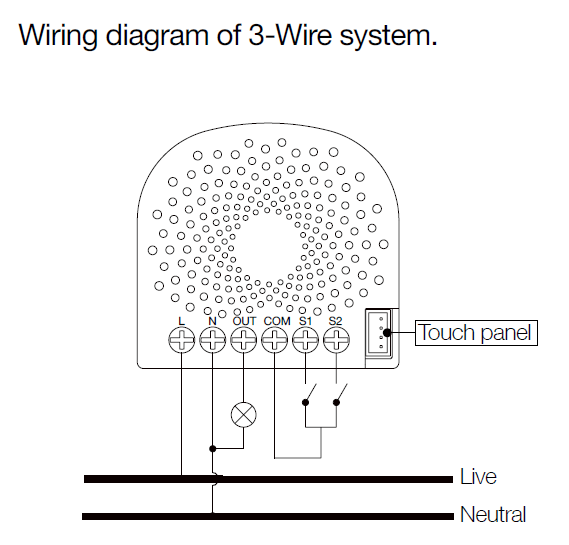
| Reset to factory default | Press and hold the Action button that you can find on the product"s housing for 20 seconds and then release. This procedure should only be used when the primary controller is missing or inoperable. |
| Inclusion | Turn the primary controller of Z-Wave network into inclusion mode, short press the products Action button that you can find on the products housing. |
| Exclusion | Turn the primary controller of Z-Wave network into exclusion mode, short press the products Action button that you can find on the products housing. |
| NIF | XXXNIF |
| Wakeup | XXXWakeupDescription |
| Protection | XXXProtection |
| FirmwareUpdate | XXXFirmwareUpdate |
| SetAssociation | XXXSetAssociation |
Association Groups:
| Group Number | Maximum Nodes | Description |
|---|---|---|
| 1 | 5 | Z-Wave Plus Lifeline.When the load state of Nano Dimmer (on/off/dim the load ) is changed, the Hail CC, Switch Multilevel Report and Basic Report (configured by parameter 80) can be sent to the associated nodes in this group. |
| 2 | 5 | Forward the Basic Set, Switch Binary Set, Switch Multilevel Start Level Change, Switch Multilevel Stop Level Change, Switch Multilevel Set, Switch all to the associated nodes in Group 2 when the Nano Dimmer receives the Basic Set, Switch Binary Set, Switch Multilevel Start Level Change, Switch Multilevel Stop Level Change, Switch Multilevel Set, Switch all commands from main controller. |
| 3 | 5 | Send Basic Set (configured by parameter 0x51 ) to the associated nodes in Group 3 when the external switch S1 is operated |
| 4 | 5 | Send Basic Set (configured by parameter 0x52) to the associated nodes in Group 4 when the external switch S2 is operated |
Configuration Parameters
Parameter 3: Current Overload Protection.
Output Load will be turned off automatically after 30 seconds and if the current overrun 1.5A. Size: 1 Byte, Default Value: 1
| Setting | Description |
|---|---|
| 0 | Disable |
| 1 | Enable |
Parameter 4: Overheat protection.
Output Load will be turned off automatically after 30 seconds and if the temperature of product inside exceeds 100°C. Size: 1 Byte, Default Value: 0
| Setting | Description |
|---|---|
| 0 | Disable |
| 1 | Enable |
Parameter 20: Configure the output status after re-power on it.
Configure the output status after re-power on it. Size: 1 Byte, Default Value: 0
| Setting | Description |
|---|---|
| 0 | Last status |
| 1 | Always on |
| 2 | Always off |
Parameter 80: To set which notification would be sent to the associated devices (Group 1)
To set which notification would be sent to the associated devices (Group 1) when the state of Nano Dimmers load is changed. Size: 1 Byte, Default Value: 0
| Setting | Description |
|---|---|
| 0 | Send Nothing |
| 1 | Send Hail CC |
| 2 | Send Basic CC report |
| 3 | Send Multilevel Switch report |
| 4 | Send Hail CC when using the manual switch to change the load state. |
Parameter 81: To set which notification would be sent to the associated nodes in association group 3
To set which notification would be sent to the associated nodes in association Group 3 when using the external switch 1 to switch the loads. Size: 1 Byte, Default Value: 1
| Setting | Description |
|---|---|
| 0 | Send Nothing |
| 1 | Send Basic Set CC |
Parameter 82: To set which notification would be sent to the associated nodes in association group 4
To set which notification would be sent to the associated nodes in association Group 4 when using the external switch 2 to switch the loads. Size: 1 Byte, Default Value: 1
| Setting | Description |
|---|---|
| 0 | Send Nothing |
| 1 | Send Basic Set CC |
Parameter 85: Set appointment 1
Set the ON time of output load. Size: 4 Byte, Default Value: 1573017
| Setting | Description |
|---|---|
| 0 - 99 | The brightness level |
| 256 - 316 | The minute value of ON time |
| 65536 - 65560 | The hour value of ON time |
| 16777215 - 16777222 | The day value (Mon to Sun) |
Parameter 86: Set appointment 2
Set the ON time of output load. Size: 4 Byte, Default Value: 2293760
| Setting | Description |
|---|---|
| 0 - 99 | The brightness level |
| 256 - 316 | The minute value of ON time |
| 65536 - 65560 | The hour value of ON time |
| 16777215 - 16777222 | The day value (Mon to Sun) |
Parameter 90: Enables/disables parameter 91 and 92 below:
Enables/disables the function of parameter 91 and 92. Size: 1 Byte, Default Value: 0
| Setting | Description |
|---|---|
| 0 | Disable |
| 1 | Enable |
Parameter 91: Set the threshold value of wattage.
Threshold change in wattage (in terms of wattage) to induce an automatic report. Size: 2 Byte, Default Value: 25
| Setting | Description |
|---|---|
| 0 - 60000 | The thershold value range is 0 to 60000 |
Parameter 92: Set the threshold value of wattage.
Threshold change in wattage (in terms of percentage) to induce an automatic report. Size: 1 Byte, Default Value: 5
| Setting | Description |
|---|---|
| 0 - 100 | The thershold value range is 0 to 100 |
Parameter 100: Set parameter 101-103 to default value.
Set parameter 101-103 to default value. Size: 1 Byte, Default Value: 0
| Setting | Description |
|---|---|
| 0 | Reset the parameter 101-103 |
Parameter 101: To set which reports need to be sent in Report group 1.
To set which reports need to be sent in Report group 1. Size: 4 Byte, Default Value: 0
| Setting | Description |
|---|---|
| 1 | Send Meter Report of voltage (V) |
| 2 | Send Meter Report of current (A) |
| 4 | Send Meter Report of wattage (W) |
| 8 | Send Meter Report of energy (kWh) |
Parameter 102: To set which reports need to be sent in Report group 2.
To set which reports need to be sent in Report group 2. Size: 1 Byte, Default Value: 0
| Setting | Description |
|---|---|
| 1 | Send Meter Report of voltage (V) |
| 2 | Send Meter Report of current (A) |
| 4 | Send Meter Report of wattage (W) |
| 8 | Send Meter Report of energy (kWh) |
Parameter 103: To set which reports need to be sent in Report group 3.
To set which reports need to be sent in Report group 3. Size: 1 Byte, Default Value: 0
| Setting | Description |
|---|---|
| 1 | Send Meter Report of voltage (V) |
| 2 | Send Meter Report of current (A) |
| 4 | Send Meter Report of wattage (W) |
| 8 | Send Meter Report of energy (kWh) |
Parameter 110: Set parameter 111-113 to default value.
Set parameter 111-113 to default value. Size: 1 Byte, Default Value: 0
| Setting | Description |
|---|---|
| 0 | Reset the parameter 111-113 |
Parameter 111: Set the interval of automatic report for Report group 1.
Set the interval of automatic report for Report group 1. Size: 4 Byte, Default Value: 3
| Setting | Description |
|---|---|
| 1 - 2147483647 | The range of interval time is 1 to 2147483647. |
Parameter 112: Set the interval of automatic report for Report group 2.
Set the interval of automatic report for Report group 2. Size: 4 Byte, Default Value: 600
| Setting | Description |
|---|---|
| 1 - 2147483647 | The range of interval time is 1 to 2147483647. |
Parameter 113: Set the interval of automatic report for Report group 2.
Set the interval of automatic report for Report group 3. Size: 4 Byte, Default Value: 600
| Setting | Description |
|---|---|
| 1 - 2147483647 | The range of interval time is 1 to 2147483647. |
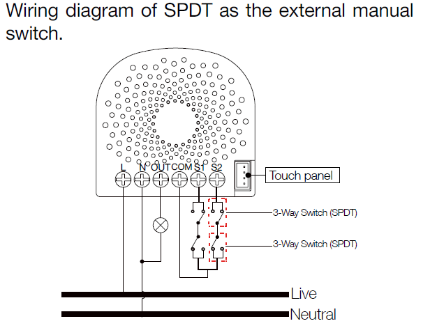
Parameter 120: Configure the external switch mode for S1.
Configure the external switch mode for S1. Size: 1 Byte, Default Value: 0
| Setting | Description |
|---|---|
| 0 | Enter automatic identification mode |
| 1 | Momentary push button mode |
| 2 | 3 way switch mode |
| 3 | 2-state switch mode |
Parameter 121: Configure the external switch mode for S2.
Configure the external switch mode for S2. Size: 1 Byte, Default Value: 0
| Setting | Description |
|---|---|
| 0 | Enter automatic identification mode |
| 1 | Momentary push button mode |
| 2 | 3 way switch mode |
| 3 | 2-state switch mode |
Parameter 122: Get the state of touch panel port
Get the state of touch panel port Size: 1 Byte, Default Value: 0
| Setting | Description |
|---|---|
| 0 | the touch panel is not connected. |
| 5 | the touch panel is connected. |
Parameter 123: Set the control destination for external switch S1
Set the control destination for external switch S1 Size: 1 Byte, Default Value: 3
| Setting | Description |
|---|---|
| 1 | control the output loads of itself. |
| 2 | control the other nodes |
| 3 | control the output loads of itself and other nodes. |
Parameter 124: Set the control destination for external switch S2
Set the control destination for external switch S2. Size: 1 Byte, Default Value: 3
| Setting | Description |
|---|---|
| 1 | control the output loads of itself. |
| 2 | control the other nodes. |
| 3 | control the output loads of itself and other nodes |
Parameter 125: Set the default dimming rate.
Set the default dimming rate. Size: 1 Byte, Default Value: 3
| Setting | Description |
|---|---|
| 1 - 255 | The value range is 1 to 255 seconds. |
Parameter 128: Get the current working mode
Get the current working mode.Note: This parameter is a Get-only parameter. Size: 1 Byte, Default Value: 0
| Setting | Description |
|---|---|
| 0 | Unknown working mode. |
| 1 | 2-wire mode |
| 2 | 3-wire mode |
Parameter 129: Set the dimming principle
Set the dimming principle. Size: 1 Byte, Default Value: 1
| Setting | Description |
|---|---|
| 0 | Trailing edge mode |
| 1 | Leading edge mode |
Parameter 130: To get what type of load the Dimmer is connected to.
To get what type of load the Dimmer is connected to.Note: This parameter is a Get-only parameter. Size: 1 Byte, Default Value: 0
| Setting | Description |
|---|---|
| 0 | Unknown load. |
| 1 | Resistive load |
| 2 | Capacitive load |
| 3 | Inductive load |
Parameter 131: Set the min brightness level that the load can reach to.
Set the min brightness level that the load can reach to. Size: 1 Byte, Default Value: 0
| Setting | Description |
|---|---|
| 0 - 99 | The level range is 0 to 99. |
Parameter 132: Set the max brightness level that the load can reach to. Note:
Set the max brightness level that the load can reach to.Note: Size: 1 Byte, Default Value: 99
| Setting | Description |
|---|---|
| 0 - 99 | The level range is 0 to 99. |
Parameter 249: Set the recognition way of load
Set the recognition way of load Size: 1 Byte, Default Value: 2
| Setting | Description |
|---|---|
| 0 | Never recognize the load when power on |
| 1 | Only recognize once when first power on |
| 2 | Recognize the load once power on |
Parameter 252: Lock/unlock configuration parameters
Lock/unlock configuration parameters. Size: 1 Byte, Default Value: 0
| Setting | Description |
|---|---|
| 0 | Unlock |
| 1 | Lock |
Parameter 255: Reset the Nano Dimmer
Reset the Nano Dimmer to factory default. Size: 4 Byte, Default Value: 0
| Setting | Description |
|---|---|
| 0 | Reset all configuration parameters to factory default setting |
| 1431655765 | Reset to factory default setting and removed from the z-wave network |
Technical Data
| Dimensions | 0.0395000x0.0197500x0.0423000 mm |
| Weight | 27 gr |
| Hardware Platform | ZM5101 |
| EAN | 4251295701127 |
| IP Class | IP 20 |
| Voltage | 230 V |
| Load | 276W |
| Device Type | Light Dimmer Switch |
| Network Operation | Always On Slave |
| Z-Wave Version | 6.51.09 |
| Certification ID | ZC10-17015388 |
| Z-Wave Product Id | 0x0086.0x0003.0x006F |
| Frequency | Europe - 868,4 Mhz |
| Maximum transmission power | 5 mW |