Widom
Energy Driven Switch Version S
SKU: WIDEWPSS


Quickstart
This is a
2. Press the push button (B) located on the top of the device once."
Important safety information
Please read this manual carefully. Failure to follow the recommendations in this manual may be dangerous or may violate the law. The manufacturer, importer, distributor and seller shall not be liable for any loss or damage resulting from failure to comply with the instructions in this manual or any other material. Use this equipment only for its intended purpose. Follow the disposal instructions. Do not dispose of electronic equipment or batteries in a fire or near open heat sources.What is Z-Wave?
Z-Wave is the international wireless protocol for communication in the Smart Home. This device is suited for use in the region mentioned in the Quickstart section.
Z-Wave ensures a reliable communication by reconfirming every message (two-way communication) and every mains powered node can act as a repeater for other nodes (meshed network) in case the receiver is not in direct wireless range of the transmitter.
This device and every other certified Z-Wave device can be used together with any other certified Z-Wave device regardless of brand and origin as long as both are suited for the same frequency range.
If a device supports secure communication it will communicate with other devices secure as long as this device provides the same or a higher level of security. Otherwise it will automatically turn into a lower level of security to maintain backward compatibility.
For more information about Z-Wave technology, devices, white papers etc. please refer to www.z-wave.info.
Product Description
The smallest device in its category worldwide, and the only device specifically intended for use both as a Relay Switch with integrated power meter, and as an Energy Meter either at the point of entry of your electrical system or on a section of the latter. Available in two versions, version S featuring an internal shunt resistor, and version C featuring an external current transformer, it is capable of measuring loads exceeding 10 KW. In addition to Power measurements, the device also provides data for Energy, Voltage, Current and Power factor.
The only device suited for use with all types of Z-Wave controller, and capable of implementing an active energy-saving management policy defined by the user according to his energy consumption, or to the amount of energy produced by his solar power system. It automatically connects and disconnects a specific load if the threshold limit is exceeded or supplies the required power, momentarily excluding non-priority loads.
Prepare for Installation / Reset
Please read the user manual before installing the product.
In order to include (add) a Z-Wave device to a network it must be in factory default state. Please make sure to reset the device into factory default. You can do this by performing an Exclusion operation as described below in the manual. Every Z-Wave controller is able to perform this operation however it is recommended to use the primary controller of the previous network to make sure the very device is excluded properly from this network.
Reset to factory default
This device also allows to be reset without any involvement of a Z-Wave controller. This procedure should only be used when the primary controller is inoperable.
Press the push button (B) located on the top of the device six consecutive times within one minute from system start-up.
Safety Warning for Mains Powered Devices
ATTENTION: only authorized technicians under consideration of the country-specific installation guidelines/norms may do works with mains power. Prior to the assembly of the product, the voltage network has to be switched off and ensured against re-switching.
Installation
WiDom Driven Switch Activation
1) Ensure that the main power switch is set in the OFF position
2) Connect the device following the diagrams provided
3) Shut the electrical box containing the device
4) Turn the main power switch back on
5) Include the device into the Z-Wave network
Electrical Connections
The device must be supplied by phase and neutral. Connections must be made according to one of the diagrams below.
Local load control
In this mode the load is controlled directly by the internal relay. The opening and closing of the relay contacts are synchronized to take place, respectively, when a zero current or voltage is reached.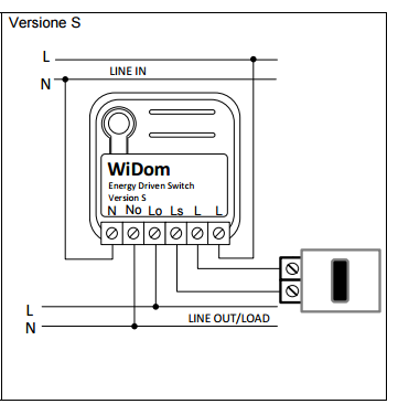
Remote load control
In this mode the device has no locally connected load, and the measures of current and power are based on all devices connected to the “LINE OUT” section of the system. The devices connected to the “LINE OUT” can be controlled individually based on the configured energy events.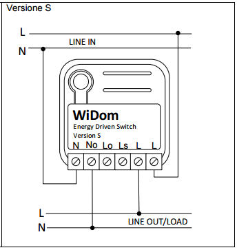
Inclusion/Exclusion
On factory default the device does not belong to any Z-Wave network. The device needs to be added to an existing wireless network to communicate with the devices of this network. This process is called Inclusion.
Devices can also be removed from a network. This process is called Exclusion. Both processes are initiated by the primary controller of the Z-Wave network. This controller is turned into exclusion respective inclusion mode. Inclusion and Exclusion is then performed doing a special manual action right on the device.
Inclusion
Press the once push button (B) located on the top of the device or push once the external Switch.Exclusion
Press the three times the push button (B)Quick trouble shooting
Here are a few hints for network installation if things dont work as expected.
- Make sure a device is in factory reset state before including. In doubt exclude before include.
- If inclusion still fails, check if both devices use the same frequency.
- Remove all dead devices from associations. Otherwise you will see severe delays.
- Never use sleeping battery devices without a central controller.
- Dont poll FLIRS devices.
- Make sure to have enough mains powered device to benefit from the meshing
Association - one device controls an other device
Z-Wave devices control other Z-Wave devices. The relationship between one device controlling another device is called association. In order to control a different device, the controlling device needs to maintain a list of devices that will receive controlling commands. These lists are called association groups and they are always related to certain events (e.g. button pressed, sensor triggers, ...). In case the event happens all devices stored in the respective association group will receive the same wireless command wireless command, typically a 'Basic Set' Command.
Association Groups:
| Group Number | Maximum Nodes | Description |
|---|---|---|
| 1 | 8 | Z-Wave Plus Lifeline:Devices to receive notifications on: status changes; energy and power levels; device local reset |
| 2 | 8 | Up Power Level Group:Devices controlled by the Up Power event |
| 3 | 8 | Down Power Level Group:Devices controlled by the Down Power event |
Configuration Parameters
Z-Wave products are supposed to work out of the box after inclusion, however certain configuration can adapt the function better to user needs or unlock further enhanced features.
IMPORTANT: Controllers may only allow configuring signed values. In order to set values in the range 128 ... 255 the value sent in the application shall be the desired value minus 256. For example: To set a parameter to 200 it may be needed to set a value of 200 minus 256 = minus 56. In case of a two byte value the same logic applies: Values greater than 32768 may needed to be given as negative values too.
Parameter 1: Device Status
Controlling the relay by means of a single click on the external switch or on the integrated button. Size: 1 Byte, Default Value: 1
| Setting | Description |
|---|---|
| 1 | TOGGLE |
| 2 | ON |
| 3 | OFF |
| 4 | IGNORE |
Parameter 20: Device status upon receipt of a Basic Set command
The final status achieved by the device when it receives a Basic Set command through the Z-Wave network. Size: 1 Byte, Default Value: 0
| Setting | Description |
|---|---|
| 1 | AS RECEIVED |
| 2 | IGNORE IF ON |
| 3 | IGNORE IF OFF |
| 4 | IGNORE |
Parameter 30: Overcurrent level
Sets the current level above which the time spent above that level is measured. Size: 2 Byte, Default Value: 1250
| Setting | Description |
|---|---|
| 0 - 1250 | Overcurren level in hundredths of Amperes |
Parameter 31: Overcurrent time
Sets the time beyond which, in the case of overcurrent at a level higher than that established in parameter 30, an OverCurrent event occurs. Size: 2 Byte, Default Value: 10
| Setting | Description |
|---|---|
| 0 - 10800 | Time in seconds |
Parameter 32: Next State
Defines the next state of the device if an overcurrent event has occurred. Size: 1 Byte, Default Value: 0
| Setting | Description |
|---|---|
| 0 | IGNORE |
| 1 | ON |
| 2 | OFF |
| 3 | TOGGLE |
Parameter 33: Meter Reset
Provides total operating time from last meter reset. When set to 0 it resets the cumulated values of energy and total operating time. Size: 4 Byte, Default Value: 1
| Setting | Description |
|---|---|
| 0 | RESET METER |
Parameter 34: Energy flow
Determines whether energy events are related to energy consumed or energy produced. Size: 1 Byte, Default Value: 1
| Setting | Description |
|---|---|
| 1 | Consumed |
| 2 | Produced |
Parameter 35: UP Power Level
Sets the level of instantaneous power in Watts beyond which time of permanence above this level is calculated. Size: 2 Byte, Default Value: 3000
| Setting | Description |
|---|---|
| 0 - 3000 | UP Power level in Watt |
Parameter 36: UP Power Time
Sets the time in seconds beyond which, if instantaneous power remains at levels exceeding threshold defined by parameter 35, a UP Power event occurs. Size: 2 Byte, Default Value: 0
| Setting | Description |
|---|---|
| 0 - 10800 | UP Power Time in seconds |
Parameter 38: UP Power Associated
Defines the status of associated devices in the presence of a UP Power event. Size: 1 Byte, Default Value: 0
| Setting | Description |
|---|---|
| 0 | OFF |
| 1 - 99 | Dimming |
| 100 | ON |
Parameter 39: DOWN Power Level
Sets the level of instantaneous power beyond which the time of permanence below this level is calculated. Size: 2 Byte, Default Value: 0
| Setting | Description |
|---|---|
| 0 - 11250 | DOWN Power Level in Watt |
Parameter 40: DOWN Power Time
Sets the time beyond which, if instantaneous power remains at levels below threshold defined by parameter 39, a DOWN Power event occurs. Size: 2 Byte, Default Value: 10
| Setting | Description |
|---|---|
| 0 - 10800 | DOWN Power Time in seconds |
Parameter 41: DOWN Power State
Defines the next state of the device in the case of a DOWN Power event occurring. Size: 1 Byte, Default Value: 0
| Setting | Description |
|---|---|
| 0 | IGNORE |
| 1 | ON |
| 2 | OFF |
| 3 | TOGGLE |
Parameter 42: DOWN Power Associated
Defines the status of associated devices in the presence of a DOWN Power event. Size: 1 Byte, Default Value: 0
| Setting | Description |
|---|---|
| 0 | OFF |
| 1 - 99 | Dimming |
| 255 | ON |
Parameter 43: Energy Level
Sets the energy level that once exceeded an Energy Limit event occurs. Size: 4 Byte, Default Value: 2000000
| Setting | Description |
|---|---|
| 0 - 2000000 | Energy Level in KWh |
Parameter 44: Energy Limit State
Defines the next state of the device in the case of an Energy Limit event occurring. Size: 1 Byte, Default Value: 0
| Setting | Description |
|---|---|
| 0 | IGNORE |
| 1 | ON |
| 2 | OFF |
| 3 | TOGGLE |
Parameter 45: Variation Instantaneous Power
Defines the percentage variation of instantaneous power determining the sending of the report. Size: 1 Byte, Default Value: 10
| Setting | Description |
|---|---|
| 1 - 100 | Power variation in percentage |
Parameter 46: Report Time Frequency
Defines the maximum time in minutes since the previous report beyond which an Instantaneous Power Report will still be sent. Size: 1 Byte, Default Value: 10
| Setting | Description |
|---|---|
| 1 - 100 | Time in minutes |
Parameter 48: Nominal Voltage
Defines the nominal voltage value in tenths of volts. Together with parameter No. 49 this is used by the automatic notification system to send reports on variations of voltage. Size: 2 Byte, Default Value: 2300
| Setting | Description |
|---|---|
| 1100 - 2300 | Nominal Voltage in Volt |
Parameter 49: Fall in maximum voltage
Defines, as a percentage, the nominal value for permitted fall in maximum voltage. Size: 1 Byte, Default Value: 10
| Setting | Description |
|---|---|
| 1 - 100 | percentage of voltage variation |
Parameter 50: Electric parameters subjected to automatic notification
Defines which electric parameters, other than power, will be subjected to automatic notification.The value to be set for this parameter must be calculated as the sum of values associated to the individual electric parameter. Size: 1 Byte, Default Value: 30
| Setting | Description |
|---|---|
| 0 | Power |
| 2 | Energy |
| 4 | Voltage |
| 8 | Current |
| 16 | Power Factor |
| 32 | Multilevel Sensor: Power Report |
Parameter 60: Start-up status
Defines the status of the device following a restart. Size: 1 Byte, Default Value: 3
| Setting | Description |
|---|---|
| 1 | ON |
| 2 | OFF |
| 3 | Status prior to restart |
Parameter 61: Configuration reset
Defines which parameters should be reset to default values. Size: 1 Byte, Default Value: 4
| Setting | Description |
|---|---|
| 0 | FACTORY RESET |
| 1 | ASSOCIATIONS RESET |
| 2 | CONFIGURATIONS RESET |
| 4 | IGNORE |
Parameter 62: Type of external switch
Defines the type of external switch connected to the device. Size: 1 Byte, Default Value: 4
| Setting | Description |
|---|---|
| 0 | IGNORE |
| 1 | BUTTON |
| 2 | SWITCH |
| 4 | AUTOMATIC RECOGNITION |
Parameter 63: Load control
Defines the load control mode. Size: 1 Byte, Default Value: 1
| Setting | Description |
|---|---|
| 1 | DIRECT CONTROL |
| 2 | CONTROL BY MEANS OF A CONTACTOR WITH NORMALLY OPEN COMMAND |
| 3 | CONTROL BY MEANS OF A CONTACTOR WITH NORMALLY CLOSED COMMAND |
| 4 | AS AN EXTERNAL INDICATOR |
Technical Data
| Dimensions | 0.0370000x0.0370000x0.0170000 mm |
| Weight | 30 gr |
| Hardware Platform | ZM5202 |
| EAN | 8059265060030 |
| IP Class | IP 20 |
| Voltage | 230 |
| Load | 12,5A |
| Device Type | On/Off Power Switch |
| Network Operation | Always On Slave |
| Z-Wave Version | 6.51.03 |
| Certification ID | ZC10-15040001 |
| Z-Wave Product Id | 0x0149.0x1214.0x0304 |
| Frequency | Europe - 868,4 Mhz |
| Maximum transmission power | 5 mW |
Supported Command Classes
- Switch All
- Association
- Association Group Information
- Configuration
- Device Reset Locally
- Firmware Update Md
- Manufacturer Specific
- Meter
- Sensor Multilevel
- Powerlevel
- Switch Binary
- Version
- Zwaveplus Info
Controlled Command Classes
- Basic
- Device Reset Locally
Explanation of Z-Wave specific terms
- Controller — is a Z-Wave device with capabilities to manage the network. Controllers are typically Gateways,Remote Controls or battery operated wall controllers.
- Slave — is a Z-Wave device without capabilities to manage the network. Slaves can be sensors, actuators and even remote controls.
- Primary Controller — is the central organizer of the network. It must be a controller. There can be only one primary controller in a Z-Wave network.
- Inclusion — is the process of adding new Z-Wave devices into a network.
- Exclusion — is the process of removing Z-Wave devices from the network.
- Association — is a control relationship between a controlling device and a controlled device.
- Wakeup Notification — is a special wireless message issued by a Z-Wave device to announces that is able to communicate.
- Node Information Frame — is a special wireless message issued by a Z-Wave device to announce its capabilities and functions.