NodOn
Z-Wave Plus Micro Smart Plug Switch F
SKU: NODEMSP3111


Quickstart
This is a
To include/add to the Z-Wave network, long press during 2 seconds to send several NIF during 30 seconds or a triple press to send a single NIF
Important safety information
Please read this manual carefully. Failure to follow the recommendations in this manual may be dangerous or may violate the law. The manufacturer, importer, distributor and seller shall not be liable for any loss or damage resulting from failure to comply with the instructions in this manual or any other material. Use this equipment only for its intended purpose. Follow the disposal instructions. Do not dispose of electronic equipment or batteries in a fire or near open heat sources.What is Z-Wave?
Z-Wave is the international wireless protocol for communication in the Smart Home. This device is suited for use in the region mentioned in the Quickstart section.
Z-Wave ensures a reliable communication by reconfirming every message (two-way communication) and every mains powered node can act as a repeater for other nodes (meshed network) in case the receiver is not in direct wireless range of the transmitter.
This device and every other certified Z-Wave device can be used together with any other certified Z-Wave device regardless of brand and origin as long as both are suited for the same frequency range.
If a device supports secure communication it will communicate with other devices secure as long as this device provides the same or a higher level of security. Otherwise it will automatically turn into a lower level of security to maintain backward compatibility.
For more information about Z-Wave technology, devices, white papers etc. please refer to www.z-wave.info.
Product Description
The NodOn Micro Smart Plug can be controlled by any kind of Z-Wave (or Z-Wave Plus) gateway or other Z-Wave controller (standalone mode) such as the NodOn Soft Remote or Octan Remote.It existed in both standard, Type E (French) or Schuko (German). Its very small design and volume allow easy integration, without obstructing nearby power holes on a power strip. Furthermore, it can perform Power and Energy Metering.The NodOn Smart Plug is based on brand new 500 series Z-Wave module from Sigma Designs, and support all the new features of Z-Wave Plus standard: Longer range (up to 40m), lower power consumption, higher data rate transmission, and many more new features.
Prepare for Installation / Reset
Please read the user manual before installing the product.
In order to include (add) a Z-Wave device to a network it must be in factory default state. Please make sure to reset the device into factory default. You can do this by performing an Exclusion operation as described below in the manual. Every Z-Wave controller is able to perform this operation however it is recommended to use the primary controller of the previous network to make sure the very device is excluded properly from this network.
Reset to factory default
This device also allows to be reset without any involvement of a Z-Wave controller. This procedure should only be used when the primary controller is inoperable.
To reset, long press during more than 5 seconds then release. Please use this procedure only when the primary controller is missing or otherwise inoperable.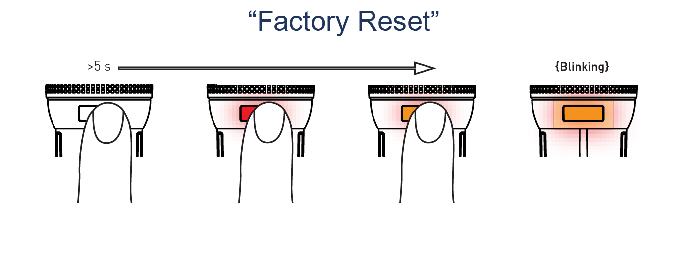
Safety Warning for Mains Powered Devices
ATTENTION: only authorized technicians under consideration of the country-specific installation guidelines/norms may do works with mains power. Prior to the assembly of the product, the voltage network has to be switched off and ensured against re-switching.
Installation
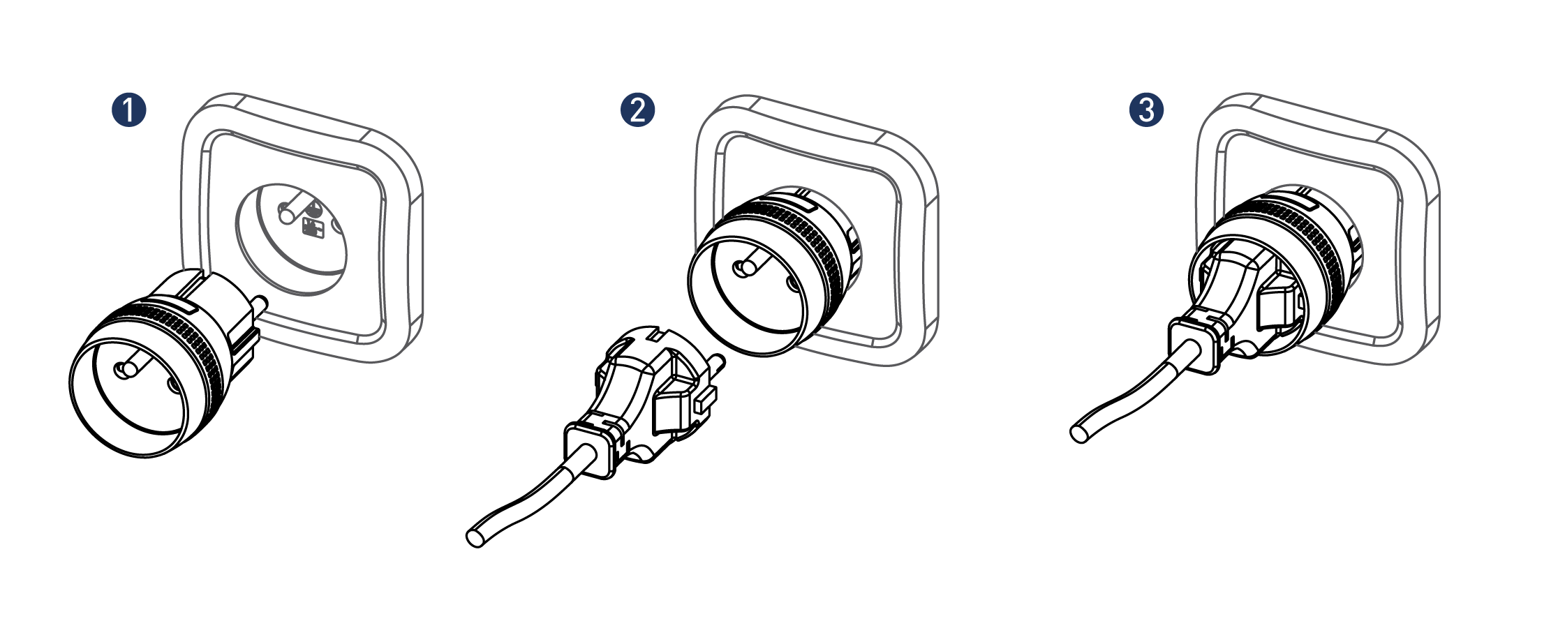
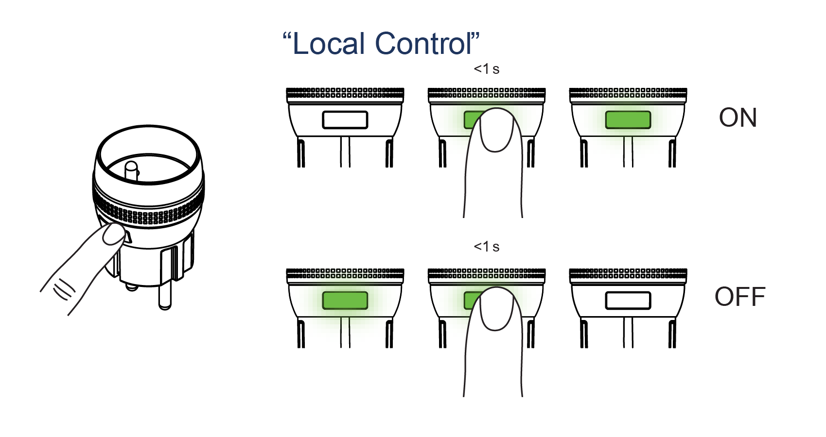
Switching ON or OFF can be done through the Micro Smart Plug local button, or any kind of Z-Wave® compatible devices, such as the NodOn® Octan Remote, the NodOn® Soft Remote or a Home Automation Gateway.
If the electrical appliance (ex.: bedside lamp) has an ON/OFF button, make sure it’s positioned on “ON”, in order that the power ON of the Micro Smart Plug will switch ON the lamp.
Inclusion/Exclusion
On factory default the device does not belong to any Z-Wave network. The device needs to be added to an existing wireless network to communicate with the devices of this network. This process is called Inclusion.
Devices can also be removed from a network. This process is called Exclusion. Both processes are initiated by the primary controller of the Z-Wave network. This controller is turned into exclusion respective inclusion mode. Inclusion and Exclusion is then performed doing a special manual action right on the device.
Inclusion
To include/add to the Z-Wave network, long press during 2 seconds to send several NIF during 30 seconds or a triple press to send a single NIFExclusion
To exclude/remove from the Z-Wave network, long press during 2 seconds to send several NIF during 30 seconds or a triple press to send a single NIFProduct Usage
Quick trouble shooting
Here are a few hints for network installation if things dont work as expected.
- Make sure a device is in factory reset state before including. In doubt exclude before include.
- If inclusion still fails, check if both devices use the same frequency.
- Remove all dead devices from associations. Otherwise you will see severe delays.
- Never use sleeping battery devices without a central controller.
- Dont poll FLIRS devices.
- Make sure to have enough mains powered device to benefit from the meshing
Association - one device controls an other device
Z-Wave devices control other Z-Wave devices. The relationship between one device controlling another device is called association. In order to control a different device, the controlling device needs to maintain a list of devices that will receive controlling commands. These lists are called association groups and they are always related to certain events (e.g. button pressed, sensor triggers, ...). In case the event happens all devices stored in the respective association group will receive the same wireless command wireless command, typically a 'Basic Set' Command.
Association Groups:
| Group Number | Maximum Nodes | Description |
|---|---|---|
| 1 | 5 | Z-Wave Plus Lifeline: This group is generally used to report information of the Micro Smart Plug to the Main Controller of the networ |
| 2 | 5 | Follow State: When the Micro Smart Plug is switched ON (respectively OFF) using the local button, it will send ON (respectively OFF) command to the associated devices. No command is sent if the Micro Smart Plug is switched ON or OFF wirelessly. This group is configurable through the parameter 3. |
| 3 | 5 | Follow Complementary State: When the Micro Smart Plug is switched ON (respectively OFF) using the local button, it will send OFF (respectively ON) command to the associated devices. No command is sent if the Micro Smart Plug is switched ON or OFF wirelessly. |
| 4 | 5 | Metering - High Threshold - Set ON/OFF:When the Micro Smart Plug reaches over the high threshold of power defined by the configuration parameter, it will send OFF or ON command to the associateddevices. This group is configurable through the parameter 25 and 27. |
| 5 | 5 | Metering - Low Threshold - Set ON/OFF:When the Micro Smart Plug reaches below the low threshold of ower defined by the configuration parameter, it will send OFF or ON command to the associated devices.This group is configurable through the parameters 26 and 27. |
| 6 | 5 | Metering Report:All the meter reports and notifications triggered by Metering parameters will be reported to the devices present in this group.This group is configurable through the parameters 21, 22, 23 and 24. |
Configuration Parameters
Z-Wave products are supposed to work out of the box after inclusion, however certain configuration can adapt the function better to user needs or unlock further enhanced features.
IMPORTANT: Controllers may only allow configuring signed values. In order to set values in the range 128 ... 255 the value sent in the application shall be the desired value minus 256. For example: To set a parameter to 200 it may be needed to set a value of 200 minus 256 = minus 56. In case of a two byte value the same logic applies: Values greater than 32768 may needed to be given as negative values too.
Parameter 1: Default State
This parameter defines the status of the Micro Smart Plug after a power outage or after being plugged. Size: 1 Byte, Default Value: 2
| Setting | Description |
|---|---|
| 0 | ON |
| 1 | OFF |
| 2 | State before power outage |
Parameter 3: Follow State
This parameter allows to enable or disable Group 2 & Group 3. Size: 1 Byte, Default Value: 3
| Setting | Description |
|---|---|
| 0 | Group 2 and Group 3 disable |
| 1 | Group 2 enable, Group 3 disable |
| 2 | Group 2 disable, Group 3 enable |
| 3 | Group 2 and Group 3 enable |
Parameter 4: Always ON
This parameter forces the Micro Smart Plug status to be ON. While enable it is not possible to switch OFF the plug (local or wireless). Size: 1 Byte, Default Value: 0
| Setting | Description |
|---|---|
| 0 | Always ON disable |
| 1 | Always ON enable |
Parameter 5: Alarm 1 Type Configuration
This parameter is to set the Alarm 1 Type. Use the Home Automation Gateway interface or our Alarm set-up form to define the value corresponding to your need. Size: 2 Byte, Default Value: 0
| Setting | Description |
|---|---|
| 0 - 65535 | To set-up your values please follow this link : www.nodon.fr/support/msp3/alarm |
Parameter 6: Alarm 1 Specifications
This parameter is to set the Alarm 1 Specifications. Use the Home Automation Gateway interface or our Alarm set-up form to define the value corresponding to your need. Size: 4 Byte, Default Value: 0
| Setting | Description |
|---|---|
| 0 - 2097151999 | To set-up your values please follow this link : www.nodon.fr/support/msp3/alarm |
Parameter 7: Alarm 2 Type Configuration
This parameter is to set the Alarm 2 Type. Use the Home Automation Gateway interface or our Alarm set-up form to define the value corresponding to your need. Size: 2 Byte, Default Value: 0
| Setting | Description |
|---|---|
| 0 - 65535 | To set-up your values please follow this link : www.nodon.fr/support/msp3/alarm |
Parameter 8: Alarm 2 Specifications
This parameter is to set the Alarm 2 Specifications. Use the Home Automation Gateway interface or our Alarm set-up form to define the value corresponding to your need. Size: 4 Byte, Default Value: 0
| Setting | Description |
|---|---|
| 0 - 2097151999 | To set-up your values please follow this link : www.nodon.fr/support/msp3/alarm |
Parameter 9: Alarm 3 Type Configuration
This parameter is to set the Alarm 3 Type. Use the Home Automation Gateway interface or our Alarm set-up form to define the value corresponding to your need. Size: 2 Byte, Default Value: 0
| Setting | Description |
|---|---|
| 0 - 65535 | To set-up your values please follow this link : www.nodon.fr/support/msp3/alarm |
Parameter 10: Alarm 3 Specifications
This parameter is to set the Alarm 3 Specifications. Use the Home Automation Gateway interface or our Alarm set-up form to define the value corresponding to your need. Size: 4 Byte, Default Value: 0
| Setting | Description |
|---|---|
| 0 - 2097151999 | To set-up your values please follow this link : www.nodon.fr/support/msp3/alarm |
Parameter 11: Alarm 4 Type Configuration
This parameter is to set the Alarm 4 Type. Use the Home Automation Gateway interface or our Alarm set-up form to define the value corresponding to your need. Size: 2 Byte, Default Value: 0
| Setting | Description |
|---|---|
| 0 - 65535 | To set-up your values please follow this link : www.nodon.fr/support/msp3/alarm |
Parameter 12: Alarm 4 Specifications
This parameter is to set the Alarm 4 Specifications. Use the Home Automation Gateway interface or our Alarm set-up form to define the value corresponding to your need. Size: 4 Byte, Default Value: 0
| Setting | Description |
|---|---|
| 0 - 2097151999 | To set-up your values please follow this link : www.nodon.fr/support/msp3/alarm |
Parameter 13: Alarm 5 Type Configuration
This parameter is to set the Alarm 5 Type. Use the Home Automation Gateway interface or our Alarm set-up form to define the value corresponding to your need. Size: 2 Byte, Default Value: 0
| Setting | Description |
|---|---|
| 0 - 65535 | To set-up your values please follow this link : www.nodon.fr/support/msp3/alarm |
Parameter 15: Alarm 6 Type Configuration
This parameter is to set the Alarm 6 Type. Use the Home Automation Gateway interface or our Alarm set-up form to define the value corresponding to your need. Size: 2 Byte, Default Value: 0
| Setting | Description |
|---|---|
| 0 - 65535 | To set-up your values please follow this link : www.nodon.fr/support/msp3/alarm |
Parameter 16: Alarm 6 Specifications
This parameter is to set the Alarm 6 Specifications. Use the Home Automation Gateway interface or our Alarm set-up form to define the value corresponding to your need. Size: 4 Byte, Default Value: 0
| Setting | Description |
|---|---|
| 0 - 2097151999 | To set-up your values please follow this link : www.nodon.fr/support/msp3/alarm |
Parameter 17: Alarm 7 Type Configuration
This parameter is to set the Alarm 7 Type. Use the Home Automation Gateway interface or our Alarm set-up form to define the value corresponding to your need. Size: 2 Byte, Default Value: 0
| Setting | Description |
|---|---|
| 0 - 2097151999 | To set-up your values please follow this link : www.nodon.fr/support/msp3/alarm |
| 0 - 65535 | To set-up your values please follow this link : www.nodon.fr/support/msp3/alarm |
Parameter 18: Alarm 7 Specifications
This parameter is to set the Alarm 7 Specifications. Use the Home Automation Gateway interface or our Alarm set-up form to define the value corresponding to your need. Size: 4 Byte, Default Value: 0
| Setting | Description |
|---|---|
| 0 - 2097151999 | To set-up your values please follow this link : www.nodon.fr/support/msp3/alarm |
Parameter 19: Alarm 8 Type Configuration
This parameter is to set the Alarm 8 Type. Use the Home Automation Gateway interface or our Alarm set-up form to define the value corresponding to your need. Size: 2 Byte, Default Value: 0
| Setting | Description |
|---|---|
| 0 - 65535 | To set-up your values please follow this link : www.nodon.fr/support/msp3/alarm |
Parameter 20: Alarm 8 Specifications
This parameter is to set the Alarm 8 Specifications. Use the Home Automation Gateway interface or our Alarm set-up form to define the value corresponding to your need. Size: 4 Byte, Default Value: 0
| Setting | Description |
|---|---|
| 0 - 2097151999 | To set-up your values please follow this link : www.nodon.fr/support/msp3/alarm |
Parameter 21: Power Auto-Sending Report
This parameter will send a power report automatically if the power value changes of x % W (Watt) compared to the last report. Size: 1 Byte, Default Value: 10
| Setting | Description |
|---|---|
| 0 | Power Auto-Polling Report Disable |
| 1 - 100 | Power Auto-Polling Report Enable with 1% (to100%) differential |
Parameter 22: Overload Report
This parameter will switch off the Micro Smart Plug in case the power is above x W (Watt) and send an alarm to the primary controller.This parameter has the highest execution priority between all the metering configurations for security reason. Size: 2 Byte, Default Value: 1840
| Setting | Description |
|---|---|
| 0 | Overload Report Disable (Not Recommended) |
| 1 - 1840 | Overload Report enable with a upper limit of 1 W (to 1840 W) |
Parameter 23: Energy Auto-Sending Report
This parameter will send a new energy report automatically if the energy value changes of x Wh (Watt-hour) compared to the last report. Size: 2 Byte, Default Value: 1000
| Setting | Description |
|---|---|
| 0 | Energy Auto-Polling Report Disable |
| 1 - 65535 | Energy Auto-Polling Report enable with 1 Wh (to 65535 Wh) diffential |
Parameter 24: Metering Pulse
Whatever other metering reports, this parameter will send one power and one energy report to the lifeline every x s (Seconds). Size: 2 Byte, Default Value: 3600
| Setting | Description |
|---|---|
| 0 | Metering Pulse disable |
| 1 - 65535 | Metering Pulse enable and send report every 1 s (to 65535 s) |
Parameter 25: Power High Threshold
This parameter defines the High Threshold power value. Size: 2 Byte, Default Value: 20
| Setting | Description |
|---|---|
| 0 | Power High Threshold disable |
| 1 - 65535 | Power High Threshold enable with the value from 1 W (to 65535 W) |
Parameter 26: Power Low Threshold
This parameter defines the Low Threshold power value. Size: 2 Byte, Default Value: 5
| Setting | Description |
|---|---|
| 0 | Power Low Threshold disable |
| 1 - 65535 | Power Low Threshold enable with the value from 1 W (to 65535 W) |
Parameter 27: Power Threshold Action
This parameter will define the Micro Smart Plug actions if the power Low and High Threshold are reached.The value may be the sum of available values. For example, if you want:- Power High Threshold Action is enable and sent ON to Group 4(3)- Power Low Threshold Action is enable and sent OFF to Group 5 (4)the parameter value must be 3+4=7. Size: 1 Byte, Default Value: 7
| Setting | Description |
|---|---|
| 0 | Power Threshold Action is disable. |
| 1 | Power High Threshold Action is enable and send the command OFF to Group 4 |
| 3 | Power High Threshold Action is enable and send the command ON to Group 4 |
| 4 | Power Low Threshold Action is enable and send the command OFF to Group 5 |
| 12 | Power Low Threshold Action is enable and send the command ON to Group 5 |
Technical Data
| Dimensions | 44 x 44 x 78 mm |
| Weight | 67 gr |
| Hardware Platform | ZM5202 |
| EAN | 3700313920602 |
| IP Class | IP 20 |
| Voltage | 230 V |
| Load | 1840 W |
| Device Type | On/Off Power Switch |
| Network Operation | Always On Slave |
| Z-Wave Version | 6.51.06 |
| Certification ID | ZC10-16045035 |
| Z-Wave Product Id | 0x0165.0x0001.0x0003 |
| Frequency | Europe - 868,4 Mhz |
| Maximum transmission power | 5 mW |
Supported Command Classes
- Association Group Information V2
- Association V2
- Basic
- Switch Binary
- Configuration
- Device Reset Locally
- Firmware Update Md V2
- Indicator
- Manufacturer Specific V2
- Meter V4
- Notification V4
- Powerlevel
- Protection V2
- Switch All
- Version V2
- Zwaveplus Info V2
Controlled Command Classes
- Application Status
- Basic
Explanation of Z-Wave specific terms
- Controller — is a Z-Wave device with capabilities to manage the network. Controllers are typically Gateways,Remote Controls or battery operated wall controllers.
- Slave — is a Z-Wave device without capabilities to manage the network. Slaves can be sensors, actuators and even remote controls.
- Primary Controller — is the central organizer of the network. It must be a controller. There can be only one primary controller in a Z-Wave network.
- Inclusion — is the process of adding new Z-Wave devices into a network.
- Exclusion — is the process of removing Z-Wave devices from the network.
- Association — is a control relationship between a controlling device and a controlled device.
- Wakeup Notification — is a special wireless message issued by a Z-Wave device to announces that is able to communicate.
- Node Information Frame — is a special wireless message issued by a Z-Wave device to announce its capabilities and functions.