Heatit (Thermo-Floor)
Z-Dim
SKU: HEAE1444444


Quickstart
This is a
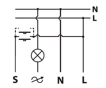
1. Switch off the mains voltage (disable the fuse).
Important safety information
Please read this manual carefully. Failure to follow the recommendations in this manual may be dangerous or may violate the law. The manufacturer, importer, distributor and seller shall not be liable for any loss or damage resulting from failure to comply with the instructions in this manual or any other material. Use this equipment only for its intended purpose. Follow the disposal instructions. Do not dispose of electronic equipment or batteries in a fire or near open heat sources.What is Z-Wave?
Z-Wave is the international wireless protocol for communication in the Smart Home. This device is suited for use in the region mentioned in the Quickstart section.
Z-Wave ensures a reliable communication by reconfirming every message (two-way communication) and every mains powered node can act as a repeater for other nodes (meshed network) in case the receiver is not in direct wireless range of the transmitter.
This device and every other certified Z-Wave device can be used together with any other certified Z-Wave device regardless of brand and origin as long as both are suited for the same frequency range.
If a device supports secure communication it will communicate with other devices secure as long as this device provides the same or a higher level of security. Otherwise it will automatically turn into a lower level of security to maintain backward compatibility.
For more information about Z-Wave technology, devices, white papers etc. please refer to www.z-wave.info.
Product Description
Heatit Z-Dim is a Z-Wave rotary dimmer for many different types of light sources.The Heatit Z-Dim works on low loads without causing the lights to flicker. It dims LED-bulbs from 1-200VA, 230V halogen and incandescent bulbs, dimable LED-drivers and electronic transformers. The dimmer is not affected by startup inrush currents. L+N leads must be connected.The dimmer is equipped with a multiway switching option. This allows you to light and dim a light source from one dimmer, and later turn it off with another one. Very practical for stairwells, long hallways etc. The dimmer fits into standard Gira System 55 frame systems.
Prepare for Installation / Reset
Please read the user manual before installing the product.
In order to include (add) a Z-Wave device to a network it must be in factory default state. Please make sure to reset the device into factory default. You can do this by performing an Exclusion operation as described below in the manual. Every Z-Wave controller is able to perform this operation however it is recommended to use the primary controller of the previous network to make sure the very device is excluded properly from this network.
Reset to factory default
This device also allows to be reset without any involvement of a Z-Wave controller. This procedure should only be used when the primary controller is inoperable.
Safety Warning for Mains Powered Devices
ATTENTION: only authorized technicians under consideration of the country-specific installation guidelines/norms may do works with mains power. Prior to the assembly of the product, the voltage network has to be switched off and ensured against re-switching.
Installation
Inclusion/Exclusion
On factory default the device does not belong to any Z-Wave network. The device needs to be added to an existing wireless network to communicate with the devices of this network. This process is called Inclusion.
Devices can also be removed from a network. This process is called Exclusion. Both processes are initiated by the primary controller of the Z-Wave network. This controller is turned into exclusion respective inclusion mode. Inclusion and Exclusion is then performed doing a special manual action right on the device.
Inclusion
Exclusion
Product Usage
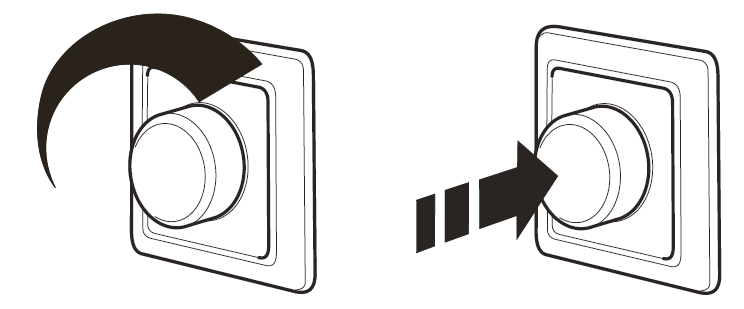
Control
Calibration
Scene Controller:
Power Metering
Quick trouble shooting
Here are a few hints for network installation if things dont work as expected.
- Make sure a device is in factory reset state before including. In doubt exclude before include.
- If inclusion still fails, check if both devices use the same frequency.
- Remove all dead devices from associations. Otherwise you will see severe delays.
- Never use sleeping battery devices without a central controller.
- Dont poll FLIRS devices.
- Make sure to have enough mains powered device to benefit from the meshing
Association - one device controls an other device
Z-Wave devices control other Z-Wave devices. The relationship between one device controlling another device is called association. In order to control a different device, the controlling device needs to maintain a list of devices that will receive controlling commands. These lists are called association groups and they are always related to certain events (e.g. button pressed, sensor triggers, ...). In case the event happens all devices stored in the respective association group will receive the same wireless command wireless command, typically a 'Basic Set' Command.
Association Groups:
| Group Number | Maximum Nodes | Description |
|---|---|---|
| 1 | 8 | Z-Wave Plus Lifeline Supports the following command classes: Meter Report: triggered according to Configuration Switch Multilevel Central Scene Device Reset Locally: triggered upon request |
| 2 | 8 | Basic Set: triggered at change of output and reflecting its state. |
| 3 | 8 | Binary Switch Set: triggered at change of output and reflecting its ON/OFF state. |
Configuration Parameters
Z-Wave products are supposed to work out of the box after inclusion, however certain configuration can adapt the function better to user needs or unlock further enhanced features.
IMPORTANT: Controllers may only allow configuring signed values. In order to set values in the range 128 ... 255 the value sent in the application shall be the desired value minus 256. For example: To set a parameter to 200 it may be needed to set a value of 200 minus 256 = minus 56. In case of a two byte value the same logic applies: Values greater than 32768 may needed to be given as negative values too.
Parameter 1: Connected Load.
The parameter defines the value of connected load. Refer to Paragraph 8 Power Metering. Size: 1 Byte, Default Value: 0
| Setting | Description |
|---|---|
| 0 | Not configured (Default) |
| 1 - 200 | 1-200 Watts connected load |
Parameter 10: Power restore level.
The parameter defines initial dimming level after power loss. Size: 1 Byte, Default Value: 50
| Setting | Description |
|---|---|
| 1 - 99 | 1% - 99%Default is 50 (50%) |
Parameter 2: Minimum Dim level.
The parameter defines the lowest dimming level of the dimmer.The value must be lower than parameter 3 Maximum Dim Level. Size: 1 Byte, Default Value: 20
| Setting | Description |
|---|---|
| 1 - 98 | 1% - 98% Default is 20 (20%) |
Parameter 3: Maximum Dim level.
The parameter defines the highest dimming level of the dimmer.The value must be higher than parameter 2 Minimum Dim Level. Size: 1 Byte, Default Value: 85
| Setting | Description |
|---|---|
| 2 - 99 | 2% - 99% Default is 85 (85%) |
Parameter 4: Total steps.
The parameter defines how many steps it should take to dim from minimum to maximum dim level. (One round = 20 steps) Size: 1 Byte, Default Value: 15
| Setting | Description |
|---|---|
| 5 - 255 | 5-255 steps. Default is 15 (3/4 round) |
Parameter 5: Double press function.
The parameter defines the double press functionality. Size: 1 Byte, Default Value: 0
| Setting | Description |
|---|---|
| 0 | Central Scene notification (Default) |
| 1 | Dim to highest level |
Parameter 6: Scene controller.
The parameter enables scene controller. Size: 1 Byte, Default Value: 1
| Setting | Description |
|---|---|
| 0 | Disabled |
| 1 | Active (Default) |
Parameter 7: Switch ON level.
The parameter defines the dimming level when restored from the OFF state by push button. Size: 1 Byte, Default Value: 0
| Setting | Description |
|---|---|
| 0 | Restores last dim level (Default) |
| 1 - 99 | 1% - 99% |
Parameter 8: Dimming Duration.
The parameter defines how long it takes to dim to the desired level.Note! Only Multilevel Switch Command Class is affected by this parameter. Size: 1 Byte, Default Value: 1
| Setting | Description |
|---|---|
| 0 | Disabled |
| 1 - 127 | Duration in seconds (1 - 127 seconds. Default is 1) |
| 128 - 255 | Duration in minutes (1 - 127 minutes) |
Parameter 9: Meter Report Interval.
The parameter defines the report interval for Power Metering. Size: 2 Byte, Default Value: 60
| Setting | Description |
|---|---|
| 0 | Disabled |
| 30 - 32767 | Duration in seconds (30 - 32 767. Default is 60) |
Technical Data
| Dimensions | 84 x 84 x 43 mm |
| Weight | 111 gr |
| Hardware Platform | ZM5101 |
| EAN | 7071236014003 |
| IP Class | IP 20 |
| Voltage | 230 V |
| Load | 0,9 A |
| Device Type | Light Dimmer Switch |
| Network Operation | Always On Slave |
| Z-Wave Version | 6.71.03 |
| Certification ID | ZC10-19106778 |
| Z-Wave Product Id | 0x019B.0x0003.0x2200 |
| Firmware Updatable | Updatable by Consumer by RF |
| Color | White |
| Electric Load Type | Dimmable ELV (Magnetic)Dimmable LEDIncandescent |
| Switch Type | Rotary Knob |
| Z-Wave Scene Type | Central Scene |
| Supported Meter Type | Electric Energy |
| Neutral Wire Required | ok |
| Frequency | Europe - 868,4 Mhz |
| Maximum transmission power | 5 mW |
Supported Command Classes
- Association Grp Info
- Association V2
- Basic V2
- Central Scene V3
- Configuration V3
- Device Reset Locally
- Firmware Update Md V4
- Manufacturer Specific V2
- Meter V3
- Multi Channel Association V3
- Powerlevel
- Security
- Security 2
- Supervision
- Switch Binary
- Switch Multilevel V4
- Transport Service V2
- Version V3
- Zwaveplus Info V2
Controlled Command Classes
- Basic V2
- Meter V3
- Switch Binary
- Switch Multilevel V4
Explanation of Z-Wave specific terms
- Controller — is a Z-Wave device with capabilities to manage the network. Controllers are typically Gateways,Remote Controls or battery operated wall controllers.
- Slave — is a Z-Wave device without capabilities to manage the network. Slaves can be sensors, actuators and even remote controls.
- Primary Controller — is the central organizer of the network. It must be a controller. There can be only one primary controller in a Z-Wave network.
- Inclusion — is the process of adding new Z-Wave devices into a network.
- Exclusion — is the process of removing Z-Wave devices from the network.
- Association — is a control relationship between a controlling device and a controlled device.
- Wakeup Notification — is a special wireless message issued by a Z-Wave device to announces that is able to communicate.
- Node Information Frame — is a special wireless message issued by a Z-Wave device to announce its capabilities and functions.