Aeotec
Recessed Door Sensor 7
SKU: AEOEZW187


Quickstart
This is a
SmartStart Inclusion. You can use this method of inclusion only if your Z-Wave gateway/controller/hub supports SmartStart.
Important safety information
Please read this manual carefully. Failure to follow the recommendations in this manual may be dangerous or may violate the law. The manufacturer, importer, distributor and seller shall not be liable for any loss or damage resulting from failure to comply with the instructions in this manual or any other material. Use this equipment only for its intended purpose. Follow the disposal instructions. Do not dispose of electronic equipment or batteries in a fire or near open heat sources.What is Z-Wave?
Z-Wave is the international wireless protocol for communication in the Smart Home. This device is suited for use in the region mentioned in the Quickstart section.
Z-Wave ensures a reliable communication by reconfirming every message (two-way communication) and every mains powered node can act as a repeater for other nodes (meshed network) in case the receiver is not in direct wireless range of the transmitter.
This device and every other certified Z-Wave device can be used together with any other certified Z-Wave device regardless of brand and origin as long as both are suited for the same frequency range.
If a device supports secure communication it will communicate with other devices secure as long as this device provides the same or a higher level of security. Otherwise it will automatically turn into a lower level of security to maintain backward compatibility.
For more information about Z-Wave technology, devices, white papers etc. please refer to www.z-wave.info.
Product Description
1. Can be embedded inside the wooden door or window.
2. Used to send out notification via Group 1 (Lifeline) when Magnet is away or near.
3. Used to control other Z-Wave device directly via Group 2.
4. Support SmartStart, which makes inclusion more convenient.
5. Support S2, which makes it more secure and reliable.
Prepare for Installation / Reset
Please read the user manual before installing the product.
In order to include (add) a Z-Wave device to a network it must be in factory default state. Please make sure to reset the device into factory default. You can do this by performing an Exclusion operation as described below in the manual. Every Z-Wave controller is able to perform this operation however it is recommended to use the primary controller of the previous network to make sure the very device is excluded properly from this network.
Reset to factory default
This device also allows to be reset without any involvement of a Z-Wave controller. This procedure should only be used when the primary controller is inoperable.
If the primary controller is missing or inoperable, you may need to reset the device to factory settings. Make sure the product is powered. To complete the reset process manually,
- Press and hold the Action Button for at least 20 seconds.
- 2 seconds, LED will shows a slow pulsing LED
- 5 seconds, LED will pulse faster
- 10 seconds, LED will flash even faster.
- 20 seconds, LED will become solid for 2 seconds to indicate it factory reset.
- You can release the action button here.
- 22 seconds. LED will breathe slowly to indicate it is factory reset.
- Release the Action Button when LED becomes slow fade-in fade-out red color.
Safety Warning for Batteries
The product contains batteries. Please remove the batteries when the device is not used. Do not mix batteries of different charging level or different brands.
Installation
The sensor is invisibly installed, so it sits within a door and its frame to provide all the information needed by a Z-Wave system for security, safety and ambiance.
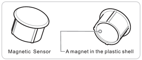
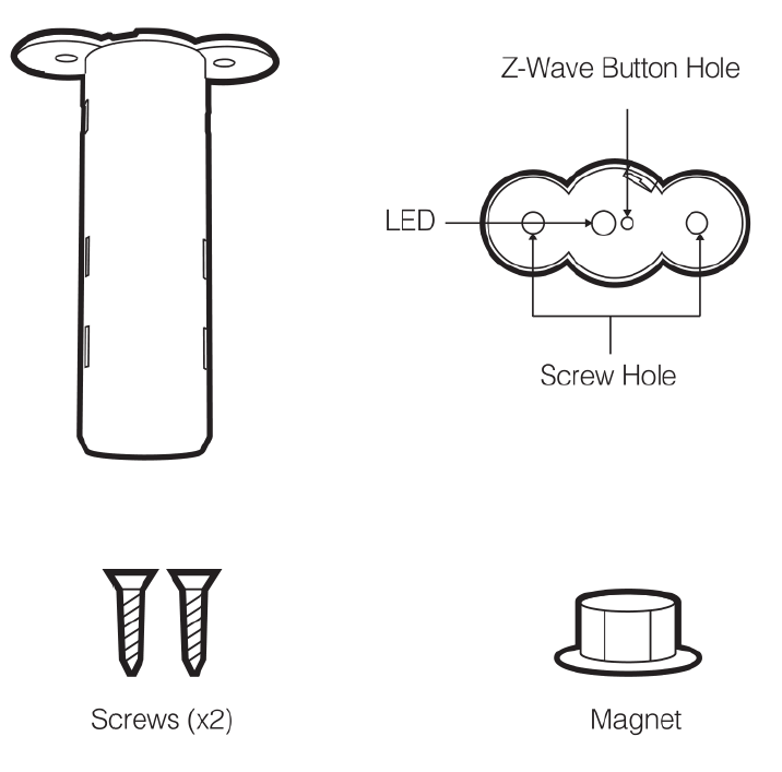
The Recessed Door Sensor GEN7 is comprised of two parts: the larger Main Sensor and the smaller Magnetic Sensor. Both of them are to be installed for proper use.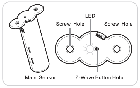
Prepare the Main Sensor
The first Step in installing your Recessed Door Sensor is to activate the Main Sensor.
1. Using a slot-head scrwedriver, remove the Main Sensor"s lid by pressing gently against its exposed connector.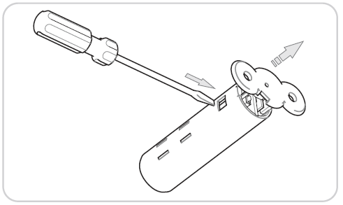
2. Seperate the Main Sensors"s two sections by first removing its lid and then removing its internal components.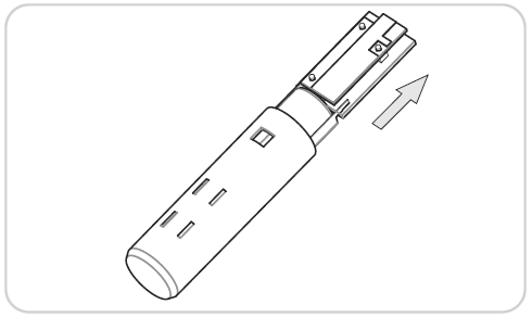
3. Remove the clear battery insulator by pulling it away from the Main Sensor.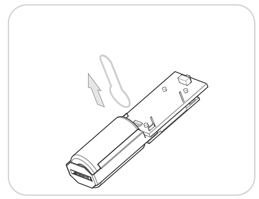
4. With the battery insulator removed, reinsert the internal components into the enclosure before reattaching its lid. Ensure that the Main Sensor"s button aligns with the buttonhole of its lid.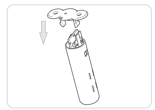
Install the Main Sensor and Magnetic Sensor
Before beginning it is important to select a suitable position for your Recessed Door Sensor. Comply with the following hints:
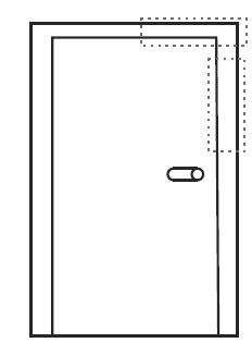
- Install at the top or the side of a door.
- Position away from metal that could interfere with the sensor"s magnetic functionality. This includes your door blade, handle or lock mechanism.
- Install in a suitable location to ensure a clear (at least 1mm) separation when the door is closed.
- Position exactly counterpart to the Magnetic Sensor.
Step 1:
Prepare a space for the Main Sensor by drilling a hole into your doorframe using a 19mm wide drill bit. The hole should be 65mm deep.
Step 2:
Drill a corresponding hole in your door. The hole should be 15mm deep and 19mm wide. The position of the hole should align exactly counterpart to hole in the door frame.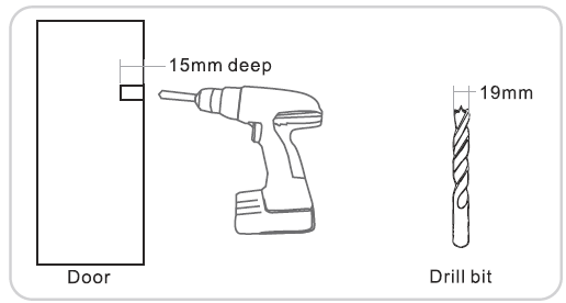
Step 3:
Insert the Main Sensor into the hole you created in the doorframe and fix it with two screws.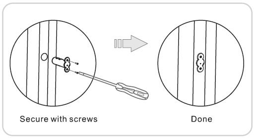
Step 4:
Place a small amount of white glue (PVA) inside the hole you created and place the Magnetic Sensor inside. Insert it by tapping gently on it with a rubber hammer.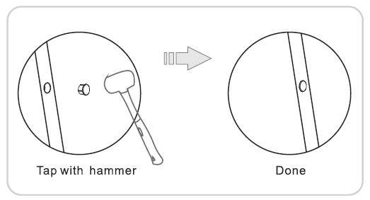
The gap between the two parts of your sensor must be at least 1 mm. Re-Affix the Sensors, if it doesnt fit.
Inclusion/Exclusion
On factory default the device does not belong to any Z-Wave network. The device needs to be added to an existing wireless network to communicate with the devices of this network. This process is called Inclusion.
Devices can also be removed from a network. This process is called Exclusion. Both processes are initiated by the primary controller of the Z-Wave network. This controller is turned into exclusion respective inclusion mode. Inclusion and Exclusion is then performed doing a special manual action right on the device.
Inclusion
1. Open the device and remove the battery protection.
2. Press the button on Recessed Door Sensor 7 once.
Exclusion
1. Press the button on Recessed Door Sensor 7 once.
Product Usage
Testing Health Connectivity.
NOTE: This health detection function is only good for determining the direct connection to the gateway (within communication distance to your gateway without any other repeater nodes).
You can determine the health of your Recessed Door Sensor 7 connectivity to your gateway using its manual button press, hold, and release function which is indicated by the LED.
Your gateway/controller/hub must support displaying Z-Wave device health in order for you to see the health of your Recessed Door Sensor 7 to your Z-Wave gateway.
Follow these steps to test the health of your Recessed Door Sensor 7 to your Z-Wave gateway/controller/hub:
- Press and hold the Z-Wave Button for 5-10 seconds to test the communication health your Range Extender 7.
- @1 second, LED will turn off.
- @2 seconds, LED will breath its LED
- @5 seconds, LED will flash its LED
- Release the Action Button to test the health.
If the LED sped up its flashing, you have held it for too long.
Once the test is finished, the Recessed Door Sensor 7 will forward a Power Level Report command to your Z-Wave gateway to display the communication quality. Some gateways do not support Power Level Command Class in its interface and may not show.
Communication to a Sleeping device (Wakeup)
This device is battery operated and turned into deep sleep state most of the time to save battery life time. Communication with the device is limited. In order to communicate with the device, a static controller C is needed in the network. This controller will maintain a mailbox for the battery operated devices and store commands that can not be received during deep sleep state. Without such a controller, communication may become impossible and/or the battery life time is significantly decreased.
This device will wakeup regularly and announce the wakeup state by sending out a so called Wakeup Notification. The controller can then empty the mailbox. Therefore, the device needs to be configured with the desired wakeup interval and the node ID of the controller. If the device was included by a static controller this controller will usually perform all necessary configurations. The wakeup interval is a tradeoff between maximal battery life time and the desired responses of the device. To wakeup the device please perform the following action: Press and hold the Action Button for at least 2 seconds but before 5 seconds.
Quick trouble shooting
Here are a few hints for network installation if things dont work as expected.
- Make sure a device is in factory reset state before including. In doubt exclude before include.
- If inclusion still fails, check if both devices use the same frequency.
- Remove all dead devices from associations. Otherwise you will see severe delays.
- Never use sleeping battery devices without a central controller.
- Dont poll FLIRS devices.
- Make sure to have enough mains powered device to benefit from the meshing
Association - one device controls an other device
Z-Wave devices control other Z-Wave devices. The relationship between one device controlling another device is called association. In order to control a different device, the controlling device needs to maintain a list of devices that will receive controlling commands. These lists are called association groups and they are always related to certain events (e.g. button pressed, sensor triggers, ...). In case the event happens all devices stored in the respective association group will receive the same wireless command wireless command, typically a 'Basic Set' Command.
Association Groups:
| Group Number | Maximum Nodes | Description |
|---|---|---|
| 1 | 5 | Lifeline group. |
| 2 | 5 | Issue Basic Set when Magnet is away or near. (The Basic Set Value is determined by Configuration Parameter 3) |
Configuration Parameters
Z-Wave products are supposed to work out of the box after inclusion, however certain configuration can adapt the function better to user needs or unlock further enhanced features.
IMPORTANT: Controllers may only allow configuring signed values. In order to set values in the range 128 ... 255 the value sent in the application shall be the desired value minus 256. For example: To set a parameter to 200 it may be needed to set a value of 200 minus 256 = minus 56. In case of a two byte value the same logic applies: Values greater than 32768 may needed to be given as negative values too.
Parameter 1: Binary Sensor Report
Enable/Disable Binary Sensor Report.Allow for backward compatibility to report Binary if Notification Report cannot be used for status changes. Size: 1 Byte, Default Value: 0
| Setting | Description |
|---|---|
| 0 | Disable. Sensor Binary Report will NOT be issued via Lifeline when Magnet is away or near. |
| 1 | Enable. Sensor Binary Report will be issued via Lifeline when Magnet is away or near. |
Parameter 2: Sensor Reports
Reverse Sensor Reports (both Sensor Binary Report and Notification Report.) Size: 1 Byte, Default Value: 0
| Setting | Description |
|---|---|
| 0 | Open Status when Magnet is away, Close Status when magnet is near. |
| 1 | Close Status when Magnet is away, Open Status when magnet is near. |
Parameter 3: Association Group 2 Settings
Configure the Basic Set value. Determine the Basic Set value to control other Z-Wave devices directly when Magnet is away or near. Size: 1 Byte, Default Value: 1
| Setting | Description |
|---|---|
| 0 | Disable completely. |
| 1 | Send Basic SET 0xFF when Magnet is away, and send Basic SET 0x00 when Magnet is near. |
| 2 | Send Basic SET 0x00 when Magnet is away, and send Basic Set 0xFF when Magnet is near. |
| 3 | Only send Basic SET 0xFF when Magnet is away. |
| 4 | Only send Basic SET 0x00 when Magnet is near. |
| 5 | Only send Basic SET 0x00 when Magnet is away. |
| 6 | Only send Basic SET 0xFF when Magnet is near. |
Parameter 4: Application Layer Retry
Configure retry number and wait time. The device supports an application retry mechanism when the application of the device has detected a transmission error when Basic Set, Sensor Binary Report or Notification Report (Access Control) message is sent out but fails to result in an ACK or a Supervision Report. Size: 2 Byte, Default Value: 0
| Setting | Description |
|---|---|
| 0 - 1535 | The Byte 1 is used to configure the number of retries. The valid value is 0-5. 0 means disable retry. The Byte 2 is used to configure the wait time between retries. The valid value is 0-255. Unit is 100ms. |
Parameter 5: Supervision Report Wait Time
Configure Supervision Report Wait Time Size: 1 Byte, Default Value: 15
| Setting | Description |
|---|---|
| 1 - 50 | Unit is 100ms. Note:Issuing Basic Set, Sensor Binary Report or Notification Report(Access Control) via association groups uses Supervision encapsulation only if sending commands with S2(or higher security) encapsulation. In other word, this parameter can be configured in any network, but works only in S2 (or higher security) network. |
Parameter 81: Led Indicator
Control LED Indicator. Determine whether the LED flash or not when sending Basic Set, Sensor Binary Report, Notification Report (Access Control) or Wake Up Notification. Size: 1 Byte, Default Value: 3
| Setting | Description |
|---|---|
| 0 | Completely disable LED. |
| 1 | LED quickly flashes only when sending Basic Set, Sensor Binary Report or Notification Report (Access Control). |
| 2 | LED activates only when sending Wake Up Notification. |
| 3 | LED quickly flashes when sending Basic Set, Sensor Binary Report or Notification Report (Access Control), and activates when sending Wake Up Notification. |
Parameter 90: Low battery threshold
Configure the low battery threshold. Induce battery report when battery level is less than or equal to threshold. Forward low battery report. Size: 1 Byte, Default Value: 30
| Setting | Description |
|---|---|
| 10 - 50 | 10%-50% |
Parameter 101: Timed battery report
Set how often battery is reported in minutes. Size: 2 Byte, Default Value: 70
| Setting | Description |
|---|---|
| 1 - 14400 | Set how often battery is reported in minutes. |
Technical Data
| Dimensions | 19,2 x 64 mm |
| Weight | 11 gr |
| Hardware Platform | ZGM130 |
| EAN | 1220000016569 |
| IP Class | IP 20 |
| Battery Type | 1 * 1/2 AA |
| Device Type | Notification Sensor |
| Network Operation | Reporting Sleeping Slave |
| Z-Wave Version | 7.11.00 |
| Certification ID | ZC12-19080008 |
| Z-Wave Product Id | 0x0371.0x0002.0x00BB |
| Color | White |
| Firmware Updatable | Updatable by Consumer by RF |
| Frequency | Europe - 868,4 Mhz |
| Maximum transmission power | 5 mW |
Supported Command Classes
- Application Status
- Association Grp Info V3
- Association V2
- Battery
- Configuration V4
- Device Reset Locally
- Firmware Update Md V5
- Manufacturer Specific V2
- Multi Channel Association V3
- Notification V8
- Powerlevel
- Security
- Security 2
- Sensor Binary V2
- Supervision
- Transport Service V2
- Version V3
- Wake Up V2
- Zwaveplus Info V2
- Indicator V3
Explanation of Z-Wave specific terms
- Controller — is a Z-Wave device with capabilities to manage the network. Controllers are typically Gateways,Remote Controls or battery operated wall controllers.
- Slave — is a Z-Wave device without capabilities to manage the network. Slaves can be sensors, actuators and even remote controls.
- Primary Controller — is the central organizer of the network. It must be a controller. There can be only one primary controller in a Z-Wave network.
- Inclusion — is the process of adding new Z-Wave devices into a network.
- Exclusion — is the process of removing Z-Wave devices from the network.
- Association — is a control relationship between a controlling device and a controlled device.
- Wakeup Notification — is a special wireless message issued by a Z-Wave device to announces that is able to communicate.
- Node Information Frame — is a special wireless message issued by a Z-Wave device to announce its capabilities and functions.