Heatit (Thermo-Floor)
Heatit ZM Thermostat 16A
SKU: HEAE4512673


Quickstart
This is a
2. Open the wall box.
3. Connect the wires according to the description in ”Installation”.
4. After verifying the connections, switch the mains supply back on.
5. Set the primary controller in add mode (security/non-security).
6. Press the configuration button 3 times in rapid succession.
7. The device LED will blink in green when the adding procedure has been successfully initiated. When the device is included in the home automation system, the LED will light up in green for 3 seconds.
Important safety information
Please read this manual carefully. Failure to follow the recommendations in this manual may be dangerous or may violate the law. The manufacturer, importer, distributor and seller shall not be liable for any loss or damage resulting from failure to comply with the instructions in this manual or any other material. Use this equipment only for its intended purpose. Follow the disposal instructions. Do not dispose of electronic equipment or batteries in a fire or near open heat sources.What is Z-Wave?
Z-Wave is the international wireless protocol for communication in the Smart Home. This device is suited for use in the region mentioned in the Quickstart section.
Z-Wave ensures a reliable communication by reconfirming every message (two-way communication) and every mains powered node can act as a repeater for other nodes (meshed network) in case the receiver is not in direct wireless range of the transmitter.
This device and every other certified Z-Wave device can be used together with any other certified Z-Wave device regardless of brand and origin as long as both are suited for the same frequency range.
If a device supports secure communication it will communicate with other devices secure as long as this device provides the same or a higher level of security. Otherwise it will automatically turn into a lower level of security to maintain backward compatibility.
For more information about Z-Wave technology, devices, white papers etc. please refer to www.z-wave.info.
Product Description
Heatit ZM Thermostat is an electronic thermostat for electrical floor heating designed for in-wall installations. The thermostat allows you to control your electrical heating through your Z-Wave network. The module is equipped with a 16A single pole relay. The thermostat requires you to connect an external sensor which is included with the device.The device can withstand a max load of 16A at 230VAC.
Prepare for Installation / Reset
Please read the user manual before installing the product.
In order to include (add) a Z-Wave device to a network it must be in factory default state. Please make sure to reset the device into factory default. You can do this by performing an Exclusion operation as described below in the manual. Every Z-Wave controller is able to perform this operation however it is recommended to use the primary controller of the previous network to make sure the very device is excluded properly from this network.
Reset to factory default
This device also allows to be reset without any involvement of a Z-Wave controller. This procedure should only be used when the primary controller is inoperable.
Press and hold the configuration button. After 3 seconds the LED will start to blink in green. After 20 seconds the LED will start to blink green rapidly for 5 seconds. You may now release the button.
Safety Warning for Mains Powered Devices
ATTENTION: only authorized technicians under consideration of the country-specific installation guidelines/norms may do works with mains power. Prior to the assembly of the product, the voltage network has to be switched off and ensured against re-switching.
Installation
Installation must be done by a qualified electrician in accordance with the national building codes.
Before installation, disconnect any power to the device mains. During installation of the device, power to the device must be disconnected AT ALL TIMES!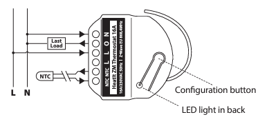
Legend:
- N Power connection (Neutral) 230VAC
- O Output. Load need to be connected between O and Neutral.
- L Power connection (Live) 230VAC.
- L Power connection (Live) 230VAC.
- NTC 10K NTC Temperature sensor.
- NTC 10K NTC Temperature sensor.
Inclusion/Exclusion
On factory default the device does not belong to any Z-Wave network. The device needs to be added to an existing wireless network to communicate with the devices of this network. This process is called Inclusion.
Devices can also be removed from a network. This process is called Exclusion. Both processes are initiated by the primary controller of the Z-Wave network. This controller is turned into exclusion respective inclusion mode. Inclusion and Exclusion is then performed doing a special manual action right on the device.
Inclusion
- Add mode is indicated on the device by a blinking green LED.
- It indicated this for 90 seconds until a timeout occurs, or until the module has been added to the network.
- To start the configuration process, press the configuration button 3 times in rapid succession.
- The LED will light up green for 3 seconds if adding is successful.
Exclusion
- Remove mode is indicated on the device by a blinking green LED.
- It indicated this for 90 seconds until a timeout occurs, or until the module has been removed from the network.
- To start the configuration process, press the configuration button 3 times in rapid succession.
- The LED will light up green for 3 seconds if removing is successful.
- The device is now ready for use with default settings.
Product Usage
PRINCIPLES OF REGULATION
The thermostat uses temperature readings retrieved from the sensor to regulate heating. When you have chosen a setpoint temperature, the thermostat will use an internal hysteresis to regulate the temperature.
HYSTERESIS
You can make changes to the thermostat hysteresis. You may change the hysteresis from between 0.3°C and 3.0°C using parameter 2. The default setting is 0.5°C. When using water-based heating, the recommended hysteresis is 1.0°C.
OVERLOAD
The device features a 16A overload protection. The overload is triggered if there is a current draw of more than 16A. The relay allows for inrush current. If the current is between 16-20A it waits for 2 seconds, if it is between 20-30A it waits for 0.5 seconds and if it is above 30A it will wait for 0.2 seconds. After the given time the device will do the following:
- Set the relay OFF
- Blink red and green
- Send a temperature report of 122°C
OVERHEATING
The device features an internal temperature sensor which prevents overheating inside the device or wall. When overheating is detected, the device will:
- Set the relay to OFF
- Blink red and green
- Send a temperature report of 121°C
CALIBRATION
Parameter 6 allows you to calibrate the temperature displayed in the controller/gateway and what the thermostat uses for regulation. If the temperature sensor readout is not correct, you can make minor changes to the temperature readout. You can calibrate the measured temperature by ±6°C degrees.
LED BLINKING PATTERNS DESCRIPTION
The device supports numerous LED blinking patterns to make it as easy as possible to identify what the device is doing.
- Error code Error status on device: Alternating red and green blinking pattern (100ms duration) for 5 seconds.
- Device Not in Network The LED will flash red when the device is not added to a Z-Wave network.
- Device Status On: Green Off: Red When the device is in OFF Mode, LEDs will be off.
- Add/RemoveWhen device enters add/remove mode the LED will flash green. If successful, the LED will light up in green for 3 seconds. If unsuccessful, the LED will light up in red for 3 seconds.
Quick trouble shooting
Here are a few hints for network installation if things dont work as expected.
- Make sure a device is in factory reset state before including. In doubt exclude before include.
- If inclusion still fails, check if both devices use the same frequency.
- Remove all dead devices from associations. Otherwise you will see severe delays.
- Never use sleeping battery devices without a central controller.
- Dont poll FLIRS devices.
- Make sure to have enough mains powered device to benefit from the meshing
Association - one device controls an other device
Z-Wave devices control other Z-Wave devices. The relationship between one device controlling another device is called association. In order to control a different device, the controlling device needs to maintain a list of devices that will receive controlling commands. These lists are called association groups and they are always related to certain events (e.g. button pressed, sensor triggers, ...). In case the event happens all devices stored in the respective association group will receive the same wireless command wireless command, typically a 'Basic Set' Command.
Association Groups:
| Group Number | Maximum Nodes | Description |
|---|---|---|
| 1 | 5 | Lifeline. (Normally used by the Z-Wave Controller) Sends |
| 2 | 5 | Send Binary Switch set commands representing the status of the internal relay. |
Configuration Parameters
Z-Wave products are supposed to work out of the box after inclusion, however certain configuration can adapt the function better to user needs or unlock further enhanced features.
IMPORTANT: Controllers may only allow configuring signed values. In order to set values in the range 128 ... 255 the value sent in the application shall be the desired value minus 256. For example: To set a parameter to 200 it may be needed to set a value of 200 minus 256 = minus 56. In case of a two byte value the same logic applies: Values greater than 32768 may needed to be given as negative values too.
Parameter 1: Operating mode
Set the thermostat mode Size: 1 Byte, Default Value: 1
| Setting | Description |
|---|---|
| 0 | Off, Thermostat will not operate |
| 1 | Heating, Thermostat mode is in heating mode |
| 2 | Cooling, Thermostat mode is in cooling mode |
Parameter 2: Temperature control hysteresis
Choose the hysteresis for the thermostat Size: 1 Byte, Default Value: 5
| Setting | Description |
|---|---|
| 3 - 30 | 0,3°C to 3,0°C,Chose the hysteresis for the thermostat. |
Parameter 3: Minimum setpoint temperature
Decide the lowest setpoint temperature allowed by the thermostat Size: 2 Byte, Default Value: 50
| Setting | Description |
|---|---|
| 50 - 400 | 5,0°C to 40,0°C,Set the minimum setpoint temperature for the thermostat |
Parameter 4: Maximum setpoint temperature
Decide the highest setpoint temperature allowed by the thermostat Size: 2 Byte, Default Value: 400
| Setting | Description |
|---|---|
| 50 - 400 | 5,0°C to 40,0°C,Set the maximum setpoint temperature for the thermostat |
Parameter 5: Setpoint
Decide the thermostat setpoint Size: 2 Byte, Default Value: 210
| Setting | Description |
|---|---|
| 50 - 400 | 5,0°C to 40,0°C,Set the setpoint temperature for the thermostat |
Parameter 6: Sensor calibration
Manually calibrate the sensor 6C Size: 1 Byte, Default Value: 0
| Setting | Description |
|---|---|
| -60 - 60 | -6,0°C to 6,0°C Calibrate the sensor 6C NB! To set a negative value, use 256 and subtract the desired value |
Parameter 7: Temperature report interval
Time interval between consecutive temperature reports Size: 2 Byte, Default Value: 1020
| Setting | Description |
|---|---|
| 30 - 65535 | Seconds, Time interval between consecutive temperature reports. |
Parameter 8: Temperature report hysteresis
Temperature reports based on change in temperature from last report Size: 1 Byte, Default Value: 10
| Setting | Description |
|---|---|
| 0 | Temperature report based on delta value is disabled. |
| 1 - 100 | 0,1°C to 10°C |
Parameter 9: Meter report interval
Time interval between consecutive meter reports Size: 2 Byte, Default Value: 1020
| Setting | Description |
|---|---|
| 30 - 65535 | Seconds, Time interval between consecutive meter reports. |
Parameter 10: Inverted output
Decides if the relay output should be inverted Size: 1 Byte, Default Value: 0
| Setting | Description |
|---|---|
| 0 | Standard output |
| 1 | Inverted output |
Parameter 11: Relay state update interval
Set the time interval of how often the device reports Binary Switch Set and thermostat mode Size: 2 Byte, Default Value: 43200
| Setting | Description |
|---|---|
| 30 - 65535 | Seconds, Time interval between consecutive temperature reports |
Technical Data
| Dimensions | 25 x 46 x 45 mm |
| Hardware Platform | ZGM130 |
| EAN | 7071236016441 |
| IP Class | IP 20 |
| Voltage | 230 |
| Load | 16A |
| Device Type | Thermostat - HVAC |
| Network Operation | Always On Slave |
| Z-Wave Version | 7.15.4 |
| Certification ID | ZC12-21100317 |
| Z-Wave Product Id | 0x019B.0x0004.0x3502 |
| Outdoor Use | ok |
| Thermostat HVAC Systems Supported | Cool OnlyHeat Only |
| Thermostat Modes | CoolHeat |
| Neutral Wire Required | ok |
| IP (Ingress Protection) Rated | ok |
| Thermostat Power Source | Mains powered (120V/240V) |
| Firmware Updatable | Updatable by Consumer by RF |
| Frequency | Europe - 868,4 Mhz |
| Maximum transmission power | 5 mW |
Supported Command Classes
- Association Grp Info V3
- Association V2
- Basic V2
- Configuration V4
- Device Reset Locally
- Firmware Update Md V5
- Indicator V3
- Manufacturer Specific V2
- Meter V3
- Multi Channel Association V3
- Powerlevel
- Security
- Security 2
- Sensor Multilevel V5
- Supervision
- Thermostat Mode V3
- Thermostat Operating State
- Thermostat Setpoint V3
- Transport Service V2
- Version V3
- Zwaveplus Info V2
Explanation of Z-Wave specific terms
- Controller — is a Z-Wave device with capabilities to manage the network. Controllers are typically Gateways,Remote Controls or battery operated wall controllers.
- Slave — is a Z-Wave device without capabilities to manage the network. Slaves can be sensors, actuators and even remote controls.
- Primary Controller — is the central organizer of the network. It must be a controller. There can be only one primary controller in a Z-Wave network.
- Inclusion — is the process of adding new Z-Wave devices into a network.
- Exclusion — is the process of removing Z-Wave devices from the network.
- Association — is a control relationship between a controlling device and a controlled device.
- Wakeup Notification — is a special wireless message issued by a Z-Wave device to announces that is able to communicate.
- Node Information Frame — is a special wireless message issued by a Z-Wave device to announce its capabilities and functions.