Heatit (Thermo-Floor)
Heatit ZM Dimmer 250W 800 series
SKU: HEAE1444449


Quickstart
This is a
Important safety information
Please read this manual carefully. Failure to follow the recommendations in this manual may be dangerous or may violate the law. The manufacturer, importer, distributor and seller shall not be liable for any loss or damage resulting from failure to comply with the instructions in this manual or any other material. Use this equipment only for its intended purpose. Follow the disposal instructions. Do not dispose of electronic equipment or batteries in a fire or near open heat sources.What is Z-Wave?
Z-Wave is the international wireless protocol for communication in the Smart Home. This device is suited for use in the region mentioned in the Quickstart section.
Z-Wave ensures a reliable communication by reconfirming every message (two-way communication) and every mains powered node can act as a repeater for other nodes (meshed network) in case the receiver is not in direct wireless range of the transmitter.
This device and every other certified Z-Wave device can be used together with any other certified Z-Wave device regardless of brand and origin as long as both are suited for the same frequency range.
If a device supports secure communication it will communicate with other devices secure as long as this device provides the same or a higher level of security. Otherwise it will automatically turn into a lower level of security to maintain backward compatibility.
For more information about Z-Wave technology, devices, white papers etc. please refer to www.z-wave.info.
Product Description
Heatit ZM Dimmer is an inwall dimmer for installation in European electrical wall boxes. The dimmer enables the user to control light sources from the Z-Wave network and/or an external switch.The Heatit ZM Dimmer works on most low loads of both LEDs and other light fixtures without causing flickering. When connecting low loads it is recommended to use a bypass.The dimmer may be connected to two external switches that can be used to control the lights, associated devices and scenes.Heatit ZM Dimmer has active power metering and it gives you real time information about your power consumption.
Prepare for Installation / Reset
Please read the user manual before installing the product.
In order to include (add) a Z-Wave device to a network it must be in factory default state. Please make sure to reset the device into factory default. You can do this by performing an Exclusion operation as described below in the manual. Every Z-Wave controller is able to perform this operation however it is recommended to use the primary controller of the previous network to make sure the very device is excluded properly from this network.
Reset to factory default
This device also allows to be reset without any involvement of a Z-Wave controller. This procedure should only be used when the primary controller is inoperable.
Press and hold the reset button. After 3 seconds the LED will start to blink green. After 20 seconds the LED will start blinking green rapidly. You may now release the button. If reset was successful the LED will light up in solid green for 3 seconds.
Safety Warning for Mains Powered Devices
ATTENTION: only authorized technicians under consideration of the country-specific installation guidelines/norms may do works with mains power. Prior to the assembly of the product, the voltage network has to be switched off and ensured against re-switching.
Installation
Installation must be done by a qualified electrician in accordance with national building codes. Before installation, disconnect the power to the device from the mains. During installation of the device, power to the device must be disconnected AT ALL TIMES!
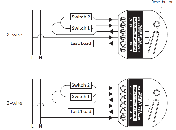
Note! The dimmer can be used in a 2 and 3-wire mode. In 2-wire mode, neutral can only be connected to the load and not the dimmer itself. The dimmer automatically detects if it is connected in 2 or 3-wire mode.
- Turn off the fuse.
- Connect the Live to the dimmer terminal marked ”L”.
- Optional: Connect the Neutral to the dimmer terminal marked ”N”.
- Connect the load terminal marked ”L” to the dimmer terminal marked
- Connect the load terminal marked “N” directly to Neutral.
- Install the dimmer in the junction box.
- Make sure that no wires are pinched.
- S1: External momentary switch. Used for dimming the load Can be used as a scene controller.
- S2: External momentary switch. Can be used for either dimming or scene controller.
Wiring
Inclusion/Exclusion
On factory default the device does not belong to any Z-Wave network. The device needs to be added to an existing wireless network to communicate with the devices of this network. This process is called Inclusion.
Devices can also be removed from a network. This process is called Exclusion. Both processes are initiated by the primary controller of the Z-Wave network. This controller is turned into exclusion respective inclusion mode. Inclusion and Exclusion is then performed doing a special manual action right on the device.
Inclusion
- To start the configuration process, press the reset button 3 times in rapid succession.
- The LED will light up in solid green for 3 seconds if add is successful.
- The device is now ready for use with default settings.
Exclusion
- To start the exclusion process, press the reset button 3 times in rapid succession.
- The LED will light up in solid green for 3 seconds if remove is successful.
- The device has been reset
Product Usage
- AUTOCALIBRATION OF MAXIMUM DIM LEVEL The dimmer supports an autocalibration feature for the maximum dim level. Autocalibration will initiate if flimmer is detected. The Maximum dim level parameter (11) will be updated automatically upon completion of the autocalibration.
- MANUAL CALIBRATION OF MINIMUM DIM LEVEL The minimum dim level may be calibrated by using the “Min.” button on the device. To adjust the minimum level, hold down the “Min.” button. The lighting will start from the lowest level and increase the dim level slowly. Release the button when the desired minimum dim level is reached. The minimum dim will now be set on the dimmer. Minimum dim level parameter (12) will be updated automatically.
- ON/OFF FUNCTIONALITYThe dimmer has support for non-dimmable loads. To activate this feature, change parameter (15) “ON/OFF functionality” to 1. When this is active, the load can no longer be dimmed, but only turned ON and OFF. When using this functionality, we recommend using the dimmer in 3-wire mode. Some light fixtures might not be compatible with 2-wire mode.
- OVERLOAD PROTECTION The dimmer supports an overload protection feature. When the connected load exceeds 250W, the dimmer will send a notification to the gateway using the Notification Command Class. (Not all gateways support this feature, so depending on the gateway you may or may not get a warning). The dimmer will continue to function normally until it reaches 300W. It will then turn off the load to protect itself.
Quick trouble shooting
Here are a few hints for network installation if things dont work as expected.
- Make sure a device is in factory reset state before including. In doubt exclude before include.
- If inclusion still fails, check if both devices use the same frequency.
- Remove all dead devices from associations. Otherwise you will see severe delays.
- Never use sleeping battery devices without a central controller.
- Dont poll FLIRS devices.
- Make sure to have enough mains powered device to benefit from the meshing
Association - one device controls an other device
Z-Wave devices control other Z-Wave devices. The relationship between one device controlling another device is called association. In order to control a different device, the controlling device needs to maintain a list of devices that will receive controlling commands. These lists are called association groups and they are always related to certain events (e.g. button pressed, sensor triggers, ...). In case the event happens all devices stored in the respective association group will receive the same wireless command wireless command, typically a 'Basic Set' Command.
Association Groups:
| Group Number | Maximum Nodes | Description |
|---|---|---|
| 1 | 1 | Lifeline |
| 2 | 5 | Basic Set - Sends Basic Set commands representing the status of the dimmer when changed. |
| 3 | 5 | Switch Multilevel - When S1 or S2 is pressed/held/released and when changed from gateway or from an association. |
Configuration Parameters
Z-Wave products are supposed to work out of the box after inclusion, however certain configuration can adapt the function better to user needs or unlock further enhanced features.
IMPORTANT: Controllers may only allow configuring signed values. In order to set values in the range 128 ... 255 the value sent in the application shall be the desired value minus 256. For example: To set a parameter to 200 it may be needed to set a value of 200 minus 256 = minus 56. In case of a two byte value the same logic applies: Values greater than 32768 may needed to be given as negative values too.
Parameter 1: Power restore level
The state the dimmer should return to once power is restored after a power failure. Size: 1 Byte, Default Value: 100
| Setting | Description |
|---|---|
| 0 | Off |
| 1 - 99 | % |
| 100 | Returns to level before power outage |
Parameter 2: Switch ON level
Defines the dimming level when restored from the OFF state. Size: 1 Byte, Default Value: 0
| Setting | Description |
|---|---|
| 0 | restore last dim level |
| 1 - 99 | % |
Parameter 3: Automatic turn OFF
Time for the dimmer to turn off automatically after turning it on. Size: 4 Byte, Default Value: 0
| Setting | Description |
|---|---|
| 0 | disabled |
| 1 - 86400 | seconds |
Parameter 4: Automatic turn ON
Time for the dimmer to turn on automatically after turning it off. Size: 4 Byte, Default Value: 0
| Setting | Description |
|---|---|
| 0 | disabled |
| 1 - 86400 | seconds |
Parameter 5: Turn off delay time
The time it takes before the dimmer turns off after turning it off. Size: 1 Byte, Default Value: 0
| Setting | Description |
|---|---|
| 0 | disabled |
| 1 - 60 | seconds |
Parameter 6: S1 functionality
Decide the S1 switch functionality. Size: 1 Byte, Default Value: 0
| Setting | Description |
|---|---|
| 0 | Single press and hold for dimming. Double press for 100%. Triple press for inclusion |
| 1 | Scene controller |
| 2 | Scene controller and Dimming |
| 3 | disabled |
Parameter 7: S2 functionality
Decide the S2 switch functionality.
Size: 1 Byte, Default Value: 1
| Setting | Description |
|---|---|
| 0 | Single press and hold for dimming. Double press for scene controller. Triple press for inclusion. |
| 1 | Scene controller. |
| 2 | Scene controller and Dimming |
| 3 | disabled |
Parameter 8: Dimming duration
Define how long it takes to dim when using the external switch. Size: 1 Byte, Default Value: 50
| Setting | Description |
|---|---|
| 0 | Instantly. |
| 1 - 100 | 0.1 - 10 sec. |
Parameter 9: Choose the dimmer curve
Choose if the dimmer uses Linear or Logarythmic dimming. Size: 1 Byte, Default Value: 0
| Setting | Description |
|---|---|
| 0 | Linear dimming |
| 1 | Logarithmic dimming. |
Parameter 10: Load dimming mode
Choose the dimming type.
Size: 1 Byte, Default Value: 0
| Setting | Description |
|---|---|
| 0 | Trailing edge |
| 1 | Leading edge |
Parameter 11: Maximum dim level
Highest dim level of the dimmer. Size: 1 Byte, Default Value: 90
| Setting | Description |
|---|---|
| 2 - 99 | % |
Parameter 12: Minimum dim level
Lowest dim level of the dimmer. Size: 1 Byte, Default Value: 15
| Setting | Description |
|---|---|
| 1 - 98 | % |
Parameter 13: Meter report threshold
Threshold for device to send meter report in W. Size: 1 Byte, Default Value: 10
| Setting | Description |
|---|---|
| 0 | Disabled |
| 1 - 250 | Watt |
Parameter 14: Meter report interval
Time interval between consecutive meter reports in seconds. Size: 2 Byte, Default Value: 810
| Setting | Description |
|---|---|
| 30 - 65535 | seconds |
Parameter 15: ON/OFF Functionality
Decide if the connected load should only turn ON/OFF and not dim Size: 1 Byte, Default Value: 0
| Setting | Description |
|---|---|
| 0 | disabled |
| 1 | enabled |
Technical Data
| Dimensions | 45 x 45 x 21 mm |
| Weight | 42 gr |
| Hardware Platform | ZG23 |
| EAN | 7071236018575 |
| IP Class | IP 20 |
| Voltage | 230V |
| Load | 250W |
| Device Type | Dimmer |
| Generic Device Class | Multilevel Switch |
| Firmware Version | 01.00 |
| Z-Wave Version | 07.12 |
| Certification ID | ZC14-23040223 |
| Z-Wave Product Id | 0x019b.0x0021.0x2101 |
| Frequency | Europe - 868,4 Mhz |
| Maximum transmission power | 5 mW |
Supported Command Classes
- Basic
- Switch Multilevel
- Meter
- Transport Service
- Association Grp Info
- Device Reset Locally
- Central Scene
- Zwaveplus Info
- Supervision
- Configuration
- Alarm
- Manufacturer Specific
- Powerlevel
- Firmware Update Md
- Association
- Version
- Indicator
- Multi Channel Association
- Security
- Security 2
Explanation of Z-Wave specific terms
- Controller — is a Z-Wave device with capabilities to manage the network. Controllers are typically Gateways,Remote Controls or battery operated wall controllers.
- Slave — is a Z-Wave device without capabilities to manage the network. Slaves can be sensors, actuators and even remote controls.
- Primary Controller — is the central organizer of the network. It must be a controller. There can be only one primary controller in a Z-Wave network.
- Inclusion — is the process of adding new Z-Wave devices into a network.
- Exclusion — is the process of removing Z-Wave devices from the network.
- Association — is a control relationship between a controlling device and a controlled device.
- Wakeup Notification — is a special wireless message issued by a Z-Wave device to announces that is able to communicate.
- Node Information Frame — is a special wireless message issued by a Z-Wave device to announce its capabilities and functions.