Heatit (Thermo-Floor)
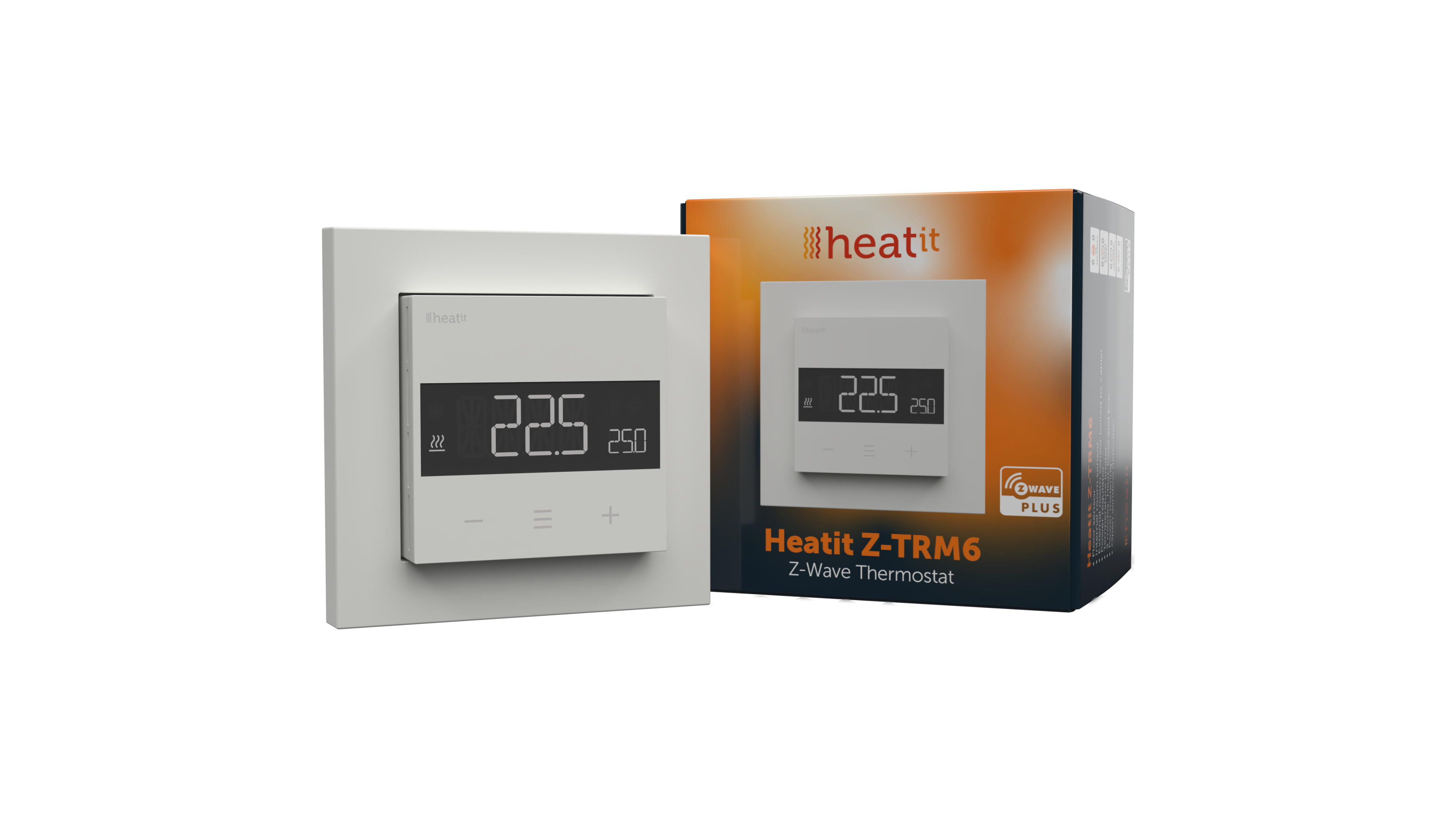
Heatit Z-TRM6 Thermostat Z-Wave 800 series (White RAL 9010)
SKU: HEAE5430567


Quickstart
This is a
Important safety information
Please read this manual carefully. Failure to follow the recommendations in this manual may be dangerous or may violate the law. The manufacturer, importer, distributor and seller shall not be liable for any loss or damage resulting from failure to comply with the instructions in this manual or any other material. Use this equipment only for its intended purpose. Follow the disposal instructions. Do not dispose of electronic equipment or batteries in a fire or near open heat sources.What is Z-Wave?
Z-Wave is the international wireless protocol for communication in the Smart Home. This device is suited for use in the region mentioned in the Quickstart section.
Z-Wave ensures a reliable communication by reconfirming every message (two-way communication) and every mains powered node can act as a repeater for other nodes (meshed network) in case the receiver is not in direct wireless range of the transmitter.
This device and every other certified Z-Wave device can be used together with any other certified Z-Wave device regardless of brand and origin as long as both are suited for the same frequency range.
If a device supports secure communication it will communicate with other devices secure as long as this device provides the same or a higher level of security. Otherwise it will automatically turn into a lower level of security to maintain backward compatibility.
For more information about Z-Wave technology, devices, white papers etc. please refer to www.z-wave.info.
Product Description
Heatit Z-TRM6 is an electronic thermostat designed for electrical heating. The thermostat can be controlled through your Z-Wave™ network or via the buttons on the front. The thermostat has a user friendly interface. The thermostat fits in standard European junction boxes and may be used with most System 55 frames. It has a sturdy metal frame for secure fastening on the junction box. The thermostat has one built-in room temperature sensor. Two additional external temperature sensors may also be connected.Heat it Z-TRM6 has active power metering, and it gives you real time information about your power consumption. It also allows you to set the power metering value manually in case of connection with a contactor.
The device has implemented ZeroX technology. This technology makes sure the relay switches at 0V when turning on and off. With this technology the thermostat will have a much longer lifetime.
The thermostat can be set up with multiple associations and can be used as a master thermostat. It can control up to 10 thermostats and 10 external relays E.g wall plugs.
Prepare for Installation / Reset
Please read the user manual before installing the product.
In order to include (add) a Z-Wave device to a network it must be in factory default state. Please make sure to reset the device into factory default. You can do this by performing an Exclusion operation as described below in the manual. Every Z-Wave controller is able to perform this operation however it is recommended to use the primary controller of the previous network to make sure the very device is excluded properly from this network.
Reset to factory default
This device also allows to be reset without any involvement of a Z-Wave controller. This procedure should only be used when the primary controller is inoperable.
- Enter the menu by holding the Center button for about 5 seconds
- Navigate in the menu with the ”+” button til you see FACT
- Press the Center button until you see “-- --” blinking in the display
- Hold for about 5 seconds to perform a reset.
- You may also initiate a reset by holding the Right and Center buttons for 60 seconds.
Safety Warning for Mains Powered Devices
ATTENTION: only authorized technicians under consideration of the country-specific installation guidelines/norms may do works with mains power. Prior to the assembly of the product, the voltage network has to be switched off and ensured against re-switching.
Installation
Installation must be done by a qualified electrician in accordance with national building codes. Before installation, disconnect the power to the device from the mains. During installation of the device, power to the device must be disconnected AT ALL TIMES!
Max tightening torque for terminal screws: 2Nm. If the cable used has multiple strands using a end sleeve is advised.
To access the terminal screws, hold the sides of the display and gently pull outwards to detach the front piece.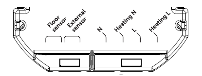
- Floor sensor NTC type: 6.8, 10, 12, 15, 22, 33, 47 or 100kΩ. Default setting: 10kΩ.
- External sensor NTC type: 6.8, 10, 12, 15, 22, 33, 47 or 100kΩ. Default setting 10kΩ.
- N Power: connection (Neutral) 230VAC.
- Heating N: Heating cable N connection.
- L Power: connection (Live) 230VAC.
- Heating L: Heating cable L connection.
Inclusion/Exclusion
On factory default the device does not belong to any Z-Wave network. The device needs to be added to an existing wireless network to communicate with the devices of this network. This process is called Inclusion.
Devices can also be removed from a network. This process is called Exclusion. Both processes are initiated by the primary controller of the Z-Wave network. This controller is turned into exclusion respective inclusion mode. Inclusion and Exclusion is then performed doing a special manual action right on the device.
Inclusion
- Hold the Center button for 5 seconds. The display will show “OFF”.
- Press the ”+” button once to see “CON” in the display.
- Start the add device process in your primary controller.
- Start the configuration mode on the thermostat by holding the Center button for approximately 2 seconds.
Exclusion
- Hold the Center button for 5 seconds. The display will show “OFF”.
- Press the ”+” button once to see “CON” in the display.
- Start the remove device process in your primary controller.
- Start the configuration mode on the thermostat by holding the Center button for approximately 2 seconds.
Product Usage
STARTUP
After powering up the device for the first time, all parameters will have default settings and the thermostat will start by asking which sensor mode should be used.THERMOSTAT CONTROLS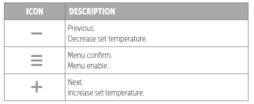
PRINCIPLES OF REGULATION
The thermostat uses temperature readings retrieved from the internal sensor and/or from external wired sensors to regulate the temperature. The thermostat will regulate the temperature using hysteresis or PWM, based on the setpoint temperature. To select either “HYST” or “PWM” you can find the “REG” menu option or use Parameter 13 “Regulation mode (“OPER”)”.
Hysteresis
Hysteresis will turn on and off the load based on the hysteresis value in comparison to the setpoint. You can make changes to the thermostat hysteresis. You may choose hysteresis values between 0.3°C and 3.0°C using Parameter 14. The default setting is 0.5°C. When using waterbased eating we recommend a hysteresis of 1.0°C.You may also change the hysteresis by entering the local settings menu and holding the Center button for 2 seconds when “REG” is displayed. Here you can choose values between 0.3 and 3.0.
Pulse-width modulation PWM
With PWM regulation enabled, the thermostat will regulate based on duty cycles. The thermostat is turned on and off in percentage intervals of the cycle. The amount of time the relay will be on is based on how far the measured temperature is from the setpoint.
LOCAL SETTINGS MENU
To enter the settings menu, hold the Center button for 5 seconds. The display will display “OFF”. You are now in the settings menu. While in the settings menu, “SET” will be displayed in the bottom right of the display. You can now scroll up and down using the Left and Right buttons. Some options have submenus. To navigate the submenus, press the Center button once to enter or exit the submenu. Press the Left and Right buttons to find your desired value and hold the Center button for 2 seconds to confirm your selection. “STOR” will appear to indicate settings are stored.
TEMPERATURE SHOWN IN DISPLAY
By default, the temperature shown on the display while in standby state is the setpoint. This may be altered with Parameter 15:”Temperature display”. It may also be changed by entering the local settings menu and holding the Center button for 2 seconds when “MODE” is displayed. You can choose between “SETT” and “RELT”. “SETT” is the Setpoint temperature and “RELT” is the real-time temperature.
STANDBY AND MAIN SCREEN
When the thermostat remains untouched for a while, it will automatically go to the standby screen. The standby will by default show the setpoint temperature.By pressing any button once, you will see the measured temperature. By pressing the Left or Right button multiple times, you will change the setpoint.
KWH VALUE IN MENU The device supports power metering to give insight into the power consumption of the heating. The total consumption of the device can be seen in the system from the “kWh” menu option. The total consumption data can be reset by holding the Center button while in the kWh menu.
SIZE OF LOAD
In the “load” menu or from Parameter 29 (size of load), the load value can be set manually if the load is not directly connected to the thermostat. The size of load can be adjusted in 100W increments up to 9900W.
CHOICE OF SENSOR
The thermostat has multiple sensors and sensor modes. This lets you configure the thermostat to work correctly in most installations. The sensors and modes may be selected from either the local settings menu or via Parameter 2; ”Sensor mode (“OPER”)”.
- Available sensor modes:
- F Floor sensor
- A Internal room sensor
- AF Internal room sensor + Floor sensor
- A2 External room sensor
- A2F External room sensor + Floor sensor
- PWER Power regulator mode (no sensor used)
NOTE: Some types of floor require that a floor sensor is connected in order to limit the floor temperature to a maximum of 27°C (check the manual from the floor manufacturer). When the thermostat is used in (AF or A2F) the floor limiter FHI is automatically set to 27°C. When using any other sensor type (A, F or A2) the minimum and maximum limits are 5°C and 40°C respectively
SELECTING SENSOR VALUE
The thermostat allows the selection of multiple different resistance values of an NTC sensor and can be selected using either the local settings menu or via Parameter 3: ”Sensor value “SEN”. The supported sensor values are as follows: 6.8, 10, 12, 15, 22, 33, 47 or 100KΩ.The factory default value is 10kΩ. When connecting both the floor sensor and the external sensor, make sure to use sensors with the same Ohm value.
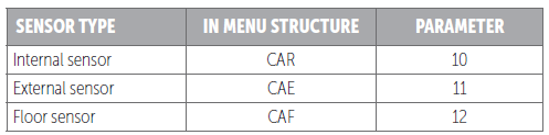
CALIBRATION
If the temperature sensor readout is not correct, you can make minor changes to the temperature readout. The temperature readings can be calibrated by ±6°C using Parameter 10, 11 and 12. The calibration can also be performed from the menu using CAR, CAE and CAF. The adjusted value will be displayed in the controller/gateway indicating what the thermostat uses for regulation.
BRIGHTNESS
Using the menu choices “BR1” and “BR2”, the brightness of the display in Active and Standby state can be changed respectively. “BR1” and “BR2” are also included in the device as Parameter 16 (BR1) and Parameter 17 (BR2).
DISPLAY ON/OFF (DON/DOFF) The thermostat has a display ON/OFF function which decides whether the display should turn completely off when in Standby. To enable/disable this function, hold the Left and Center buttons for 10 seconds. The display will show “DOFF” when the function is activated and “DON” when the function is disabled. When operating any button, the display will light up.
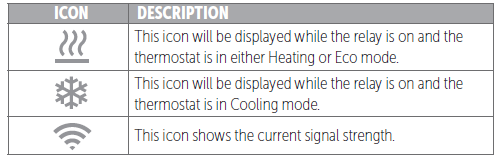
DISPLAY ICONS
CHILD LOCK
Child lock is a function for disabling the buttons from the display locally. It will show “LOCK” when attempting to operate it while the function is enabled. To enable or disable the function, hold the Left and Right buttons for 10 seconds.Enabling the function will show “LOCK” in the display, disabling the function will show “OPEN”.
OPEN WINDOW DETECTION OWD
Open Window Detection (OWD) is a function which will reduce the thermostat setpoint on detection of an open window. This happens when the temperature sensor registers a rapid temperature drop.When OWD is active, the setpoint is reduced to 5°C in order not to waste energy. OWD will automatically be cancelled if OWD has been active for more than 1 hour, or if the temperature increases by 3°C. OWD can also be cancelled manually by increasing/decreasing the setpoint with the Left and Right buttons.By default, OWD is not enabled. The feature may be enabled by selecting “OWD” from the menu. Choose between options “OFF” and “ON”. It can also be enabled by setting parameter 26 (open window detection) to 1.
ERROR CODES
- Err Adding fail. See “Inclusion/Exclusion”.
- Err1 Internal error. Most probably a faulty unit. Replace unit.
- Err2 Z-Wave error. Most probably a faulty unit. Replace unit
- Err3 Internal error. Most probably a faulty unit. Replace unit.
- Err4 Floor sensor error. You have chosen F, AF or A2F sensor mode without having a floor sensor connected, or the sensor may be damaged.
- Err5 External sensor error. You have chosen A2 or A2F sensor mode without having an external sensor connected, or the sensor may be damaged.
- Err6 Overheating. Contact your electrician.
- Err7 Overload. Contact your electrician.
Quick trouble shooting
Here are a few hints for network installation if things dont work as expected.
- Make sure a device is in factory reset state before including. In doubt exclude before include.
- If inclusion still fails, check if both devices use the same frequency.
- Remove all dead devices from associations. Otherwise you will see severe delays.
- Never use sleeping battery devices without a central controller.
- Dont poll FLIRS devices.
- Make sure to have enough mains powered device to benefit from the meshing
Association - one device controls an other device
Z-Wave devices control other Z-Wave devices. The relationship between one device controlling another device is called association. In order to control a different device, the controlling device needs to maintain a list of devices that will receive controlling commands. These lists are called association groups and they are always related to certain events (e.g. button pressed, sensor triggers, ...). In case the event happens all devices stored in the respective association group will receive the same wireless command wireless command, typically a 'Basic Set' Command.
Association Groups:
| Group Number | Maximum Nodes | Description |
|---|---|---|
| 1 | 1 | Lifeline |
| 2 | 10 | Send Binary Switch set commands based on the internal relay state. |
| 3 | 10 | Sends Thermostat Setpoint set commands based on own setpoint to allow for use as master thermostat |
| 4 | 10 | Sends Thermostat Mode set commands based on own mode to allow for use as master thermostat. |
Configuration Parameters
Z-Wave products are supposed to work out of the box after inclusion, however certain configuration can adapt the function better to user needs or unlock further enhanced features.
IMPORTANT: Controllers may only allow configuring signed values. In order to set values in the range 128 ... 255 the value sent in the application shall be the desired value minus 256. For example: To set a parameter to 200 it may be needed to set a value of 200 minus 256 = minus 56. In case of a two byte value the same logic applies: Values greater than 32768 may needed to be given as negative values too.
Parameter 1: Disable buttons
Disable buttons, must be enabled through the parameter, or turned back on locally by holding the center and right button for 30 seconds until the display shows “UNLK”. Size: 1 Byte, Default Value: 0
| Setting | Description |
|---|---|
| 0 | Enabled |
| 1 | Disabled |
Parameter 2: Sensor mode (OPER)
Choose which sensors the thermostat should use for regulation. Size: 1 Byte, Default Value: 1
| Setting | Description |
|---|---|
| 0 | F, Floor sensor |
| 1 | A, Internal sensor (Default) |
| 2 | AF, Internal sensor with floor sensor limitations |
| 3 | A2, External sensor |
| 4 | A2F, External sensor with floor sensor limitations |
| 5 | PWER, Power regulator mode |
Parameter 3: Sensor value (SEN)
Select the resistance value of the connected NTC. Size: 1 Byte, Default Value: 0
| Setting | Description |
|---|---|
| 0 | 10KΩ |
| 1 | 12KΩ |
| 2 | 15KΩ |
| 3 | 22KΩ |
| 4 | 33KΩ |
| 5 | 47KΩ |
| 6 | 6.8KΩ |
| 7 | 100KΩ |
Parameter 4: Internal sensor min temp limit
Decides the lowest temperature allowed by the thermostat when using sensor mode A. Size: 2 Byte, Default Value: 50
| Setting | Description |
|---|---|
| 50 - 400 | 5°C to 40°C |
Parameter 5: Floor sensor min temp limit
Devices the lowest temperature allowed by the thermostat when using sensor mode AF, F, A2F. Size: 2 Byte, Default Value: 50
| Setting | Description |
|---|---|
| 50 - 400 | 5°C to 40°C |
Parameter 6: External sensor min temp limit
Decides the lowest temperature allowed by the thermostat when using sensor mode A2, A2F. Size: 2 Byte, Default Value: 50
| Setting | Description |
|---|---|
| 50 - 400 | 5°C to 40°C |
Parameter 7: Internal sensor max temp limit
Decide the highest temperature allowed by the thermostat when using sensor mode A. Size: 2 Byte, Default Value: 400
| Setting | Description |
|---|---|
| 50 - 400 | 5°C to 40°C |
Parameter 8: Floor sensor max temp limit
Decide the highest temperature allowed by the thermostat when using sensor mode AF, F, A2F. Size: 2 Byte, Default Value: 400
| Setting | Description |
|---|---|
| 50 - 400 | 5°C to 40°C |
Parameter 9: External sensor max temp limit
Decide the highest temperature allowed by the thermostat when using sensor mode A2, A2F. Size: 2 Byte, Default Value: 400
| Setting | Description |
|---|---|
| 50 - 400 | 5°C to 40°C |
Parameter 10: Internal sensor calibration (CAR)
Manually calibrate sensor A ±6°C. Size: 1 Byte, Default Value: 0
| Setting | Description |
|---|---|
| -60 - 60 | -6.0°C to 6.0°C |
Parameter 11: Floor sensor calibration (CAF)
Manually calibrate sensor F ±6°C. Size: 1 Byte, Default Value: 0
| Setting | Description |
|---|---|
| -60 - 60 | -6.0°C to 6.0°C |
Parameter 12: External sensor calibration (CAE)
Manually calibrate sensor A2 ±6°C. Size: 1 Byte, Default Value: 0
| Setting | Description |
|---|---|
| -60 - 60 | -6.0°C to 6.0°C |
Parameter 13: Regulation mode (REG)
Choose between regulation modes PWM and Hysteresis Size: 1 Byte, Default Value: 0
| Setting | Description |
|---|---|
| 0 | Hysteresis |
| 1 | PWM regulation |
Parameter 14: Temperature control hysteresis (HYST)
Choose the hysteresis used when regulation mode is set to HYST. Size: 1 Byte, Default Value: 5
| Setting | Description |
|---|---|
| 3 - 30 | 0.3°C to 3.0°C. |
Parameter 15: Temperature display
Select what is shown on the display during Standby state. Size: 1 Byte, Default Value: 0
| Setting | Description |
|---|---|
| 0 | Display setpoint temperature. |
| 1 | Display measured temperature. |
Parameter 16: Active display brightness (BR1)
Configure the brightness of the display during active state. Size: 1 Byte, Default Value: 10
| Setting | Description |
|---|---|
| 1 - 10 | 10 to 100% |
Parameter 17: Standby display brightness (BR2)
Configure the brightness of the display during standby state. Size: 1 Byte, Default Value: 5
| Setting | Description |
|---|---|
| 1 - 10 | 10 to 100% |
Parameter 18: Temperature report interval
Set the time interval between consecutive temperature reports. Size: 2 Byte, Default Value: 840
| Setting | Description |
|---|---|
| 30 - 65535 | seconds |
Parameter 19: Temperature report hysteresis
Set the change in temperature required to send a temperature report based on change. Size: 1 Byte, Default Value: 10
| Setting | Description |
|---|---|
| 1 - 100 | 0.1°C to 10°C |
Parameter 20: Meter report interval
Set the time interval between consecutive meter reports. Size: 2 Byte, Default Value: 840
| Setting | Description |
|---|---|
| 30 - 65535 | seconds |
Parameter 21: Action after error
Decide how the device should react when the overload / overheating features has turned OFF relay. Size: 2 Byte, Default Value: 0
| Setting | Description |
|---|---|
| 0 | Device will turn off and show an error in the display. |
| 10 - 65535 | seconds |
Parameter 22: Heating setpoint
Set setpoint for Heating mode
Size: 2 Byte, Default Value: 210
| Setting | Description |
|---|---|
| 50 - 400 | 5°C to 40°C |
Parameter 23: Cooling setpoint
Set setpoint for Cooling mode.
Size: 2 Byte, Default Value: 180
| Setting | Description |
|---|---|
| 50 - 400 | 5°C to 40°C |
Parameter 24: ECO setpoint
Set setpoint for ECO mode.
Size: 2 Byte, Default Value: 180
| Setting | Description |
|---|---|
| 50 - 400 | 5°C to 40°C. |
Parameter 25: Power regulator active time
Set the % of time the relay should be active when using PWER mode. (30-minute duty cycle). Size: 1 Byte, Default Value: 2
| Setting | Description |
|---|---|
| 1 - 10 | 10 to 100%. |
Parameter 26: Thermostat state update interval
Set the time interval of how often the device updates Thermostat Setpoint set, Thermostat Mode set and Binary set to associated devices. Size: 2 Byte, Default Value: 43200
| Setting | Description |
|---|---|
| 0 | Sends only when changed. |
| 30 - 65535 | seconds |
Parameter 27: Operating Mode (MODE)
Set the thermostat mode.
Size: 1 Byte, Default Value: 1
| Setting | Description |
|---|---|
| 0 | OFF |
| 1 | Heating mode |
| 2 | Cooling mode |
| 3 | ECO mode |
Parameter 28: Open window detection
Choose to enable or disable the Open windows detection. Size: 1 Byte, Default Value: 0
| Setting | Description |
|---|---|
| 0 | disabled |
| 1 | enabeled |
Parameter 29: Size of load
Allows the user to decide the power consumption of the connected load in 100W increments. Size: 1 Byte, Default Value: 0
| Setting | Description |
|---|---|
| 0 | Uses power metering values. |
| 1 - 99 | 100 - 9900 Watt |
Technical Data
| Dimensions | 75 x 75 x 50 mm |
| Weight | 168 gr |
| Hardware Platform | ZG23 |
| EAN | 7071236018070 |
| IP Class | IP 20 |
| Voltage | 230V |
| Load | 16A |
| Device Type | Thermostat |
| Firmware Version | 01.00 |
| Z-Wave Version | 07.12 |
| Certification ID | ZC14-23080311 |
| Z-Wave Product Id | 0x019b.0x0030.0x3001 |
| Frequency | Europe - 868,4 Mhz |
| Maximum transmission power | 5 mW |
Supported Command Classes
- Basic
- Sensor Multilevel
- Meter
- Thermostat Mode
- Thermostat Operating State
- Thermostat Setpoint
- Transport Service
- Association Grp Info
- Device Reset Locally
- Zwaveplus Info
- Multi Channel
- Supervision
- Configuration
- Alarm
- Manufacturer Specific
- Powerlevel
- Protection
- Firmware Update Md
- Association
- Version
- Indicator
- Multi Channel Association
- Security
- Security 2
Explanation of Z-Wave specific terms
- Controller — is a Z-Wave device with capabilities to manage the network. Controllers are typically Gateways,Remote Controls or battery operated wall controllers.
- Slave — is a Z-Wave device without capabilities to manage the network. Slaves can be sensors, actuators and even remote controls.
- Primary Controller — is the central organizer of the network. It must be a controller. There can be only one primary controller in a Z-Wave network.
- Inclusion — is the process of adding new Z-Wave devices into a network.
- Exclusion — is the process of removing Z-Wave devices from the network.
- Association — is a control relationship between a controlling device and a controlled device.
- Wakeup Notification — is a special wireless message issued by a Z-Wave device to announces that is able to communicate.
- Node Information Frame — is a special wireless message issued by a Z-Wave device to announce its capabilities and functions.