Shelly
Shelly Qubino Wave i4
SKU: ALREZWE_W_I4


Quickstart
This is a
1. To enter the Setting mode, quickly press and hold the S button on the Device until the LED turns solid blue.
2. Quickly release and then press and hold (> 2s) the S button on the Device until the blue LED starts blinking in Mode 3. Releasing the S button will start the Learn mode.
3. The blue LED will be blinking in Mode 2 during the adding process.
4. The green LED will be blinking in Mode 1 if the Device is successfully added to a Z-Wave® network.
Important safety information
Please read this manual carefully. Failure to follow the recommendations in this manual may be dangerous or may violate the law. The manufacturer, importer, distributor and seller shall not be liable for any loss or damage resulting from failure to comply with the instructions in this manual or any other material. Use this equipment only for its intended purpose. Follow the disposal instructions. Do not dispose of electronic equipment or batteries in a fire or near open heat sources.What is Z-Wave?
Z-Wave is the international wireless protocol for communication in the Smart Home. This device is suited for use in the region mentioned in the Quickstart section.
Z-Wave ensures a reliable communication by reconfirming every message (two-way communication) and every mains powered node can act as a repeater for other nodes (meshed network) in case the receiver is not in direct wireless range of the transmitter.
This device and every other certified Z-Wave device can be used together with any other certified Z-Wave device regardless of brand and origin as long as both are suited for the same frequency range.
If a device supports secure communication it will communicate with other devices secure as long as this device provides the same or a higher level of security. Otherwise it will automatically turn into a lower level of security to maintain backward compatibility.
For more information about Z-Wave technology, devices, white papers etc. please refer to www.z-wave.info.
Product Description
The Device is a 4-digital inputs module (110-240 V AC) that controls other devices within the Z-Wave network. It enables manual activation or deactivation of scenes through a switch/push-button.
Prepare for Installation / Reset
Please read the user manual before installing the product.
In order to include (add) a Z-Wave device to a network it must be in factory default state. Please make sure to reset the device into factory default. You can do this by performing an Exclusion operation as described below in the manual. Every Z-Wave controller is able to perform this operation however it is recommended to use the primary controller of the previous network to make sure the very device is excluded properly from this network.
Reset to factory default
This device also allows to be reset without any involvement of a Z-Wave controller. This procedure should only be used when the primary controller is inoperable.
1. To enter the Setting mode, quickly press and hold the S button on the Device until the LED turns solid blue.
2. Press the S button multiple times until the LED turns solid red.
3. Press and hold (> 2s) S button on the Device until the red LED starts blinking in Mode 3. Releasing the S button will start the factory reset.
4. During factory reset, the LED will turn solid green for about 1s, then the blue and red LED will start blinking in Mode 3 for approx. 2s.
5. The blue LED will be blinking in Mode 1 if the Factory reset is successful.
Safety Warning for Mains Powered Devices
ATTENTION: only authorized technicians under consideration of the country-specific installation guidelines/norms may do works with mains power. Prior to the assembly of the product, the voltage network has to be switched off and ensured against re-switching.
Installation
Basic wiring diagram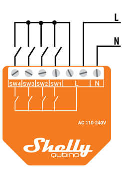
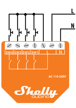
N...Neutral terminal
L... Live terminal (110–240 V AC)
SW 1... Switch/push-button input terminal
SW 2... Switch/push-button input terminal
SW 3... Switch/push-button input terminal
SW 4... Switch/push-button input terminal
Inclusion/Exclusion
On factory default the device does not belong to any Z-Wave network. The device needs to be added to an existing wireless network to communicate with the devices of this network. This process is called Inclusion.
Devices can also be removed from a network. This process is called Exclusion. Both processes are initiated by the primary controller of the Z-Wave network. This controller is turned into exclusion respective inclusion mode. Inclusion and Exclusion is then performed doing a special manual action right on the device.
Inclusion
1. To enter the Setting mode, quickly press and hold the S button on the Device until the LED turns solid blue.2. Quickly release and then press and hold (> 2s) the S button on the Device until the blue LED starts blinking in Mode 3. Releasing the S button will start the Learn mode.
3. The blue LED will be blinking in Mode 2 during the adding process.
4. The green LED will be blinking in Mode 1 if the Device is successfully added to a Z-Wave® network.
Exclusion
1. To enter the Setting mode, quickly press and hold the S button on the Device until the LED turns solid blue.2. Quickly release and then press and hold (> 2s) the S button on the Device until the blue LED starts blinking in Mode 3. Releasing the S button will start the LEARN MODE.
3. The blue LED will be blinking in Mode 2 during the removing process.
4. The blue LED will be blinking in Mode 1 if the Device is successfully removed from a Z-Wave® network.
Product Usage
Switch/push-button connected to input terminals
The device supports Central Scene Command Class and when a button is single pressed, double pressed, held and released, it will transmit a scene notification together with scene number (1,2,3 or 4)
NOTE: Switch type is not supported for triggering central scene notifications
Push-button connected to input terminals
If the switch is configured as a push-button:Scene number = 0X01, 0x02, 0x03, 0x04
- Short press: Central scene notification “Key pressed 1 time=0x00” with scene number 0X01, 0X02, 0X03, 0X04 is sent and send command to the associated devices in associated groups 4, 6, 8, 10 (check chapter Z-Wave Association).
- 2x Short press: Central scene notification “Key pressed 2 time=0x00” is sent.
- Press and hold: Central scene notification “Key held down =0x02” is sent and Send command to the associated devices in associated group 5, 7, 9, 11 (check chapter Z-Wave Association).
- Release: Central scene notification “Key released =0x01” is sent and Send command to the associated devices in associated group 5 (check chapter Z-Wave Association).
- Change switch position once: Send the command to the associated devices in associated groups 4 and 5, 6 and 7, 8 and 9, 10 and 11 (check chapter Z-Wave Association).
- Switching to Close switch-memory contact: send command to the associated devices in associated groups 4 and 5, 6 and 7, 8 and 9, 10 and 11 (check chapter Z-Wave Association) according to switch state.
- Switching to Open switch-memory contact: send command to the associated devices in associated groups 4 and 5, 6 and 7, 8 and 9, 10 and 11 (check chapter Z-Wave Association) according to switch state.
- switch off its own relay
- sends the Notification Report to the Gateway (Overheat detected)
- the led lights react as specified above (check blinking mode for Overheat detected)
S button and operating modes
- Normal mode
- Setting in progress mode
- Setting mode (with S button)
- Settings mode is required to start desired procedure for example: adding (inclusion), removing (exclusion), factory reset etc. It has a limited time of operation. After the procedure in Setting mode is concluded, the Device goes automatically into Normal mode.
- Entering to Setting mode:
- Quickly press and hold the S button on the Device until the LED turns solid blue
- An additional quick press on the S button means menu change in infinite loop
- Menu LED status has a timeout of 10s before entering again into Normal state
Mode 1 0,5s On/2s Off
Mode 2 0,5s On/0,5s Off
Mode 3 0,1s On/0,1s Off
Mode 4 (1x to 6x - 0,2s On/0,2s Off) + 2s Off
Mode 5 0,2s On blue/0,2s On red
Quick trouble shooting
Here are a few hints for network installation if things dont work as expected.
- Make sure a device is in factory reset state before including. In doubt exclude before include.
- If inclusion still fails, check if both devices use the same frequency.
- Remove all dead devices from associations. Otherwise you will see severe delays.
- Never use sleeping battery devices without a central controller.
- Dont poll FLIRS devices.
- Make sure to have enough mains powered device to benefit from the meshing
Firmware-Update over the Air
This device is capable of receiving a new firmware 'over the air'. The update function
needs to be supported by the central controller. Once the controller starts the update
process, perform the following action to confirm the firmware update:
Shelly Updates
Association - one device controls an other device
Z-Wave devices control other Z-Wave devices. The relationship between one device controlling another device is called association. In order to control a different device, the controlling device needs to maintain a list of devices that will receive controlling commands. These lists are called association groups and they are always related to certain events (e.g. button pressed, sensor triggers, ...). In case the event happens all devices stored in the respective association group will receive the same wireless command wireless command, typically a 'Basic Set' Command.
Association Groups:
| Group Number | Maximum Nodes | Description |
|---|---|---|
| 1 | 9 | Lifeline |
| 4 | 9 | SW1: BASIC_SET : set On / Off state at the associated device |
| 5 | 9 | SW1: SWITCH_MULTILEVEL_START_LEVEL_CHANGE : initiate a transition to a new level (increase or decrease light intensity in case of dimmer, or move shutter up or down, …), SWITCH_MULTILEVEL_STOP_LEVEL_CHANGE : stop an ongoing transition (stop increase or decrease light intensity in case of dimmer, or stop moving shutter up or down, …) |
| 6 | 9 | SW2: BASIC_SET : set On / Off state at the associated device |
| 7 | 9 | SW2: SWITCH_MULTILEVEL_START_LEVEL_CHANGE : initiate a transition to a new level (increase or decrease light intensity in case of dimmer, or move shutter up or down, …), SWITCH_MULTILEVEL_STOP_LEVEL_CHANGE : stop an ongoing transition (stop increase or decrease light intensity in case of dimmer, or stop moving shutter up or down, …) |
| 8 | 9 | SW3: BASIC_SET : set On / Off state at the associated device |
| 9 | 9 | SW3: SWITCH_MULTILEVEL_START_LEVEL_CHANGE : initiate a transition to a new level (increase or decrease light intensity in case of dimmer, or move shutter up or down, …), SWITCH_MULTILEVEL_STOP_LEVEL_CHANGE : stop an ongoing transition (stop increase or decrease light intensity in case of dimmer, or stop moving shutter up or down, …) |
| 10 | 9 | SW4: BASIC_SET : set On / Off state at the associated device |
| 11 | 9 | SW4: SWITCH_MULTILEVEL_START_LEVEL_CHANGE : initiate a transition to a new level (increase or decrease light intensity in case of dimmer, or move shutter up or down, …), SWITCH_MULTILEVEL_STOP_LEVEL_CHANGE : stop an ongoing transition (stop increase or decrease light intensity in case of dimmer, or stop moving shutter up or down, …) |
| 2 | 9 | Multichannel Association SWITCH_BINARY_REPORT SW1 - SW4 |
| 3 | 9 | Multichannel Association SW1 - SW4, SWITCH_MULTILEVEL_START_LEVEL_CHANGE : initiate a transition to a new level (increase or decrease light intensity in case of dimmer, or move shutter up or down, …), SWITCH_MULTILEVEL_STOP_LEVEL_CHANGE : stop an ongoing transition (stop increase or decrease light intensity in case of dimmer, or stop moving shutter up or down, …) |
Configuration Parameters
Z-Wave products are supposed to work out of the box after inclusion, however certain configuration can adapt the function better to user needs or unlock further enhanced features.
IMPORTANT: Controllers may only allow configuring signed values. In order to set values in the range 128 ... 255 the value sent in the application shall be the desired value minus 256. For example: To set a parameter to 200 it may be needed to set a value of 200 minus 256 = minus 56. In case of a two byte value the same logic applies: Values greater than 32768 may needed to be given as negative values too.
Parameter 1: SW (SW1) Switch type
This parameter defines how the Device should treat the switch (which type) connected to the SW (SW1) terminal. Size: 1 Byte, Default Value: 0
| Setting | Description |
|---|---|
| 0 | momentary switch |
| 1 | toggle switch |
| 2 | toggle switch (Device changes status when switch changes status) |
Parameter 2: SW (SW2) Switch type
This parameter defines how the Device should treat the switch (which type) connected to the SW (SW2) terminal. Size: 1 Byte, Default Value: 0
| Setting | Description |
|---|---|
| 0 | momentary switch |
| 1 | toggle switch |
| 2 | toggle switch (Device changes status when switch changes status) |
Parameter 3: SW (SW3) Switch type
This parameter defines how the Device should treat the switch (which type) connected to the SW (SW3) terminal. Size: 1 Byte, Default Value: 0
| Setting | Description |
|---|---|
| 0 | momentary switch |
| 1 | toggle switch |
| 2 | toggle switch (Device changes status when switch changes status) |
Parameter 4: SW (SW4) Switch type
This parameter defines how the Device should treat the switch (which type) connected to the SW (SW1) terminal. Size: 1 Byte, Default Value: 0
| Setting | Description |
|---|---|
| 0 | momentary switch |
| 1 | toggle switch |
| 2 | toggle switch (Device changes status when switch changes status) |
Parameter 105: LED Signalisation intensity
This parameter determines the intensity of the LED on the Device. Some Devices have RGB LEDs and some have Blue/Red LEDs, but all are dimmable. Size: 1 Byte, Default Value: 100
| Setting | Description |
|---|---|
| 0 - 100 | % |
Parameter 120: Factory Reset
Size: 1 Byte, Default Value: 0
| Setting | Description |
|---|---|
| 0 | no action |
| 1 | Factory Reset |
Technical Data
| Dimensions | 37 x 42 x 16 mm |
| Weight | 16 gr |
| Hardware Platform | ZGM230 |
| EAN | 3800235269077 |
| IP Class | IP IP20 |
| Voltage | 230V |
| Firmware Version | 0b.04 |
| Z-Wave Version | 07.14 |
| Certification ID | ZC14-24010389 |
| Z-Wave Product Id | 0x0460.0x0009.0x0081 |
| Frequency | Europe - 868,4 Mhz |
| Maximum transmission power | 5 mW |
Supported Command Classes
- Basic
- Switch Binary
- Transport Service
- Association Grp Info
- Device Reset Locally
- Central Scene
- Zwaveplus Info
- Multi Channel
- Supervision
- Configuration
- Alarm
- Manufacturer Specific
- Powerlevel
- Firmware Update Md
- Association
- Version
- Indicator
- Multi Channel Association
- Security
- Security 2
Explanation of Z-Wave specific terms
- Controller — is a Z-Wave device with capabilities to manage the network. Controllers are typically Gateways,Remote Controls or battery operated wall controllers.
- Slave — is a Z-Wave device without capabilities to manage the network. Slaves can be sensors, actuators and even remote controls.
- Primary Controller — is the central organizer of the network. It must be a controller. There can be only one primary controller in a Z-Wave network.
- Inclusion — is the process of adding new Z-Wave devices into a network.
- Exclusion — is the process of removing Z-Wave devices from the network.
- Association — is a control relationship between a controlling device and a controlled device.
- Wakeup Notification — is a special wireless message issued by a Z-Wave device to announces that is able to communicate.
- Node Information Frame — is a special wireless message issued by a Z-Wave device to announce its capabilities and functions.