Aeotec
Aeotec Home Energy Meter 8 - 2 clamps
SKU: AEOUZWA046C2A60


Quickstart
This is a
SmartStart QR code scanning:
If your Z-Wave gateway supports SmartStart, you can scan the QR code on the Home Energy Meter 8 to automatically pair the sensor if your Z-Wave hub supports this.
For most other hubs:
Important safety information
Please read this manual carefully. Failure to follow the recommendations in this manual may be dangerous or may violate the law. The manufacturer, importer, distributor and seller shall not be liable for any loss or damage resulting from failure to comply with the instructions in this manual or any other material. Use this equipment only for its intended purpose. Follow the disposal instructions. Do not dispose of electronic equipment or batteries in a fire or near open heat sources.What is Z-Wave?
Z-Wave is the international wireless protocol for communication in the Smart Home. This device is suited for use in the region mentioned in the Quickstart section.
Z-Wave ensures a reliable communication by reconfirming every message (two-way communication) and every mains powered node can act as a repeater for other nodes (meshed network) in case the receiver is not in direct wireless range of the transmitter.
This device and every other certified Z-Wave device can be used together with any other certified Z-Wave device regardless of brand and origin as long as both are suited for the same frequency range.
If a device supports secure communication it will communicate with other devices secure as long as this device provides the same or a higher level of security. Otherwise it will automatically turn into a lower level of security to maintain backward compatibility.
For more information about Z-Wave technology, devices, white papers etc. please refer to www.z-wave.info.
Product Description
With the Aeotec Home Energy Meter 8 (Z-Wave 800), you can optimize your energy consumption in real-time and efficiently reduce your electricity costs. This device precisely measures your power usage and excess energy from solar panels, ensuring smart energy utilization. Thanks to SmartThings integration, you can monitor your energy anytime, anywhere.
Prepare for Installation / Reset
Please read the user manual before installing the product.
In order to include (add) a Z-Wave device to a network it must be in factory default state. Please make sure to reset the device into factory default. You can do this by performing an Exclusion operation as described below in the manual. Every Z-Wave controller is able to perform this operation however it is recommended to use the primary controller of the previous network to make sure the very device is excluded properly from this network.
Reset to factory default
This device also allows to be reset without any involvement of a Z-Wave controller. This procedure should only be used when the primary controller is inoperable.
- Make sure the device has been powered and expose the Action Button by removing the HEM 8 from its back mount.
- Press and hold the button for 10+ seconds, then release the action button. 3. If the reset was successful, the LED will flash slowly to indicate it was factory reset.
Safety Warning for Mains Powered Devices
ATTENTION: only authorized technicians under consideration of the country-specific installation guidelines/norms may do works with mains power. Prior to the assembly of the product, the voltage network has to be switched off and ensured against re-switching.
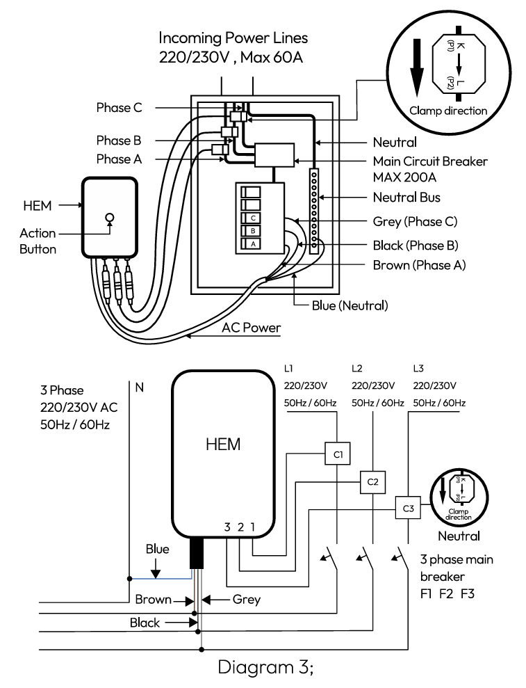
Installation
Wiring your Home Energy Meter.
To perform the electrical installation for your Home Energy Meter (HEM), utilize the previous images to determine the phase version of the HEM and to also illustrate the following steps 3 through 7.
- Turn off the home’s main electricity breaker and open the main circuit box panel.
- Connect each clamp to the HEM using the clamp connector and screw them tight.
- Clip the clamps of the HEM around the incoming electricity cables that connect to the main circuit breaker.
- Connect AC Wire to the meter using the AC Wire Connector.
- Insert the HEM’s neutral AC Wire into the main circuit breaker’s neutral bus terminal.
- Insert the HEM’s live AC Wire into the main circuit breaker’s live terminal.
- Replace the main circuit box panel.
- Turn the main breaker back on.
If the home’s circuit box is made of metal, it is recommended that the Main Body of the meter be installed outside of the circuit box. Placing the meter inside the circuit box could degrade the quality of the radio signal and negatively impact its wireless range. To assist with such an installation, each meter is weatherized to the IP44 international standard. This makes it resistant to rain and snow when installed vertically.
To mount or place the Home Energy Meter (HEM).
- Remove the backing plate from the back of the HEM.
- Affix the plate to the selected wall space using the provided screws. The plate should be installed vertically and aligned so that the wires of the HEM are at the bottom.
- 3. Attach the HEM to the backing plate.
Inclusion/Exclusion
On factory default the device does not belong to any Z-Wave network. The device needs to be added to an existing wireless network to communicate with the devices of this network. This process is called Inclusion.
Devices can also be removed from a network. This process is called Exclusion. Both processes are initiated by the primary controller of the Z-Wave network. This controller is turned into exclusion respective inclusion mode. Inclusion and Exclusion is then performed doing a special manual action right on the device.
Inclusion
SmartStart QR code scanning:If your Z-Wave gateway supports SmartStart, you can scan the QR code on the Home Energy Meter 8 to automatically pair the sensor if your Z-Wave hub supports this.
For most other hubs:
- Set your Z-Wave hub to connect new Z-Wave devices.
- Tap the Home Energy Meter 8 action button once.
- If prompted, scan the QR code or enter the 5-digit DSK code.
Exclusion
- Set your Z-Wave hub to remove Z-Wave devices.
- Tap the Home Energy Meter 8 action button once.
Product Usage
Once Home Energy Meter 8 is installed, depending on the Z-Wave hub/controller that you are using and the integration level of the sensor, many entities/devices should appear. There are multiple child nodes, and different outputs for both consumption and production of power, among many other reporting variables between each. Organizing (including hiding reports that you do not want to see) your entities may or may not be possible between each hub - Depending on how many clamps Home Energy Meter 8 has, will determine how many child devices there are.Each endpoint can report V, A, W, kWh, Power Factor, kVar, kVarh for each clamp or total report.
3 Clamp Version (7 reports * 10 endpoints = 70 individual possible reports)
- Endpoint 1 - Clamp 1 Consumption
- Endpoint 2 - Clamp 1 Production
- Endpoint 3 - Clamp 2 Consumption
- Endpoint 4 - Clamp 2 Production
- Endpoint 5 - Clamp 3 Consumption
- Endpoint 6 - Clamp 3 Production
- Endpoint 7 - Sum of Consumption for all Clamps (Clamp 1 + 2)
- Endpoint 8 - Sum of Production for all Clamps (Clamp 1 + 2)
- Endpoint 9 - Net power consumption of power and energy (consumption - generation = net total consumption)
- Endpoint 10 - Net power generation of power and energy (generation - consumption = net total generation)
Quick trouble shooting
Here are a few hints for network installation if things dont work as expected.
- Make sure a device is in factory reset state before including. In doubt exclude before include.
- If inclusion still fails, check if both devices use the same frequency.
- Remove all dead devices from associations. Otherwise you will see severe delays.
- Never use sleeping battery devices without a central controller.
- Dont poll FLIRS devices.
- Make sure to have enough mains powered device to benefit from the meshing
Association - one device controls an other device
Z-Wave devices control other Z-Wave devices. The relationship between one device controlling another device is called association. In order to control a different device, the controlling device needs to maintain a list of devices that will receive controlling commands. These lists are called association groups and they are always related to certain events (e.g. button pressed, sensor triggers, ...). In case the event happens all devices stored in the respective association group will receive the same wireless command wireless command, typically a 'Basic Set' Command.
Association Groups:
| Group Number | Maximum Nodes | Description |
|---|---|---|
| 1 | 5 | Lifeline |
Configuration Parameters
Z-Wave products are supposed to work out of the box after inclusion, however certain configuration can adapt the function better to user needs or unlock further enhanced features.
IMPORTANT: Controllers may only allow configuring signed values. In order to set values in the range 128 ... 255 the value sent in the application shall be the desired value minus 256. For example: To set a parameter to 200 it may be needed to set a value of 200 minus 256 = minus 56. In case of a two byte value the same logic applies: Values greater than 32768 may needed to be given as negative values too.
Parameter 3: Threshold Check
Enable selective reporting only when power change reaches a certain threshold or percentage set in Parameter 4-19 below. This is used to reduce network traffic. Size: 1 Byte, Default Value: 1
| Setting | Description |
|---|---|
| 0 | Disable |
| 1 | Enable |
Parameter 4: Import watt threshold (Total)
Size: 2 Byte, Default Value: 50
| Setting | Description |
|---|---|
| 5 - 60000 | Watt |
Parameter 5: Import watt threshold (Phase A)
Size: 2 Byte, Default Value: 50
| Setting | Description |
|---|---|
| 5 - 60000 | Watt |
Parameter 6: Import watt threshold (Phase B)
Size: 2 Byte, Default Value: 50
| Setting | Description |
|---|---|
| 5 - 60000 | Watt |
Parameter 7: Import watt threshold (Phase C)
Size: 2 Byte, Default Value: 50
| Setting | Description |
|---|---|
| 5 - 60000 | Watt |
Parameter 8: Export watt threshold(Total)
Size: 2 Byte, Default Value: 50
| Setting | Description |
|---|---|
| 5 - 60000 | Watt |
Parameter 9: Export watt threshold (Phase A)
Size: 2 Byte, Default Value: 50
| Setting | Description |
|---|---|
| 5 - 60000 | Watt |
Parameter 10: Export watt threshold (Phase B)
Size: 2 Byte, Default Value: 50
| Setting | Description |
|---|---|
| 5 - 60000 | Watt |
Parameter 11: Export watt threshold (Phase C)
Size: 2 Byte, Default Value: 50
| Setting | Description |
|---|---|
| 5 - 60000 | Watt |
Parameter 12: Import watt percent threshold (Total)
Size: 1 Byte, Default Value: 20
| Setting | Description |
|---|---|
| 1 - 100 | % |
Parameter 13: Import watt percent threshold (Phase A)
Size: 1 Byte, Default Value: 20
| Setting | Description |
|---|---|
| 1 - 100 | % |
Parameter 14: Import watt percent threshold (Phase B)
Size: 1 Byte, Default Value: 20
| Setting | Description |
|---|---|
| 1 - 100 | % |
Parameter 15: Import watt percent threshold (Phase C)
Size: 1 Byte, Default Value: 20
| Setting | Description |
|---|---|
| 1 - 100 | % |
Parameter 16: Export watt percent threshold (Total)
Size: 1 Byte, Default Value: 20
| Setting | Description |
|---|---|
| 1 - 100 | % |
Parameter 17: Export watt percent threshold (Phase A)
Size: 1 Byte, Default Value: 20
| Setting | Description |
|---|---|
| 1 - 100 | % |
Parameter 18: Export watt percent threshold (Phase B)
Size: 1 Byte, Default Value: 20
| Setting | Description |
|---|---|
| 1 - 100 | % |
Parameter 19: Export watt percent threshold (Phase C)
Size: 1 Byte, Default Value: 20
| Setting | Description |
|---|---|
| 1 - 100 | % |
Parameter 100: Set 101-106 to default
Size: 1 Byte, Default Value: 0
| Setting | Description |
|---|---|
| 1 | Set 101-106 to default |
Parameter 101: Automatic Report list 1 (Import)
Please refer to the table in the original manual. Size: 4 Byte, Default Value: 50529027
| Setting | Description |
|---|---|
| 0 - 4294967295 | Value |
Parameter 102: Automatic Report list 2 (Import)
Please refer to the table in the original manual. Size: 4 Byte, Default Value: 202116108
| Setting | Description |
|---|---|
| 0 - 4294967295 | Value |
Parameter 103: Automatic Report list 3 (Import)
Please refer to the table in the original manual. Size: 4 Byte, Default Value: 4042322160
| Setting | Description |
|---|---|
| 0 - 4294967295 | Value |
Parameter 104: Automatic Report list 1 (Export)
Please refer to the table in the original manual. Size: 4 Byte, Default Value: 50529027
| Setting | Description |
|---|---|
| 1 - 4294967295 | Value |
Parameter 105: Automatic Report list 2 (Export)
Please refer to the table in the original manual. Size: 4 Byte, Default Value: 202116108
| Setting | Description |
|---|---|
| 1 - 4294967295 | Value |
Parameter 106: Automatic Report list 3 (Export)
Please refer to the table in the original manual. Size: 4 Byte, Default Value: 4042322160
| Setting | Description |
|---|---|
| 1 - 4294967295 | Value |
Parameter 110: Set 111-116 to default
Size: 1 Byte, Default Value: 0
| Setting | Description |
|---|---|
| 1 | Set 111-116 to default |
Parameter 111: Automatic list 1 Interval Time (Import)
Timing detection time of Checklist 1. Size: 4 Byte, Default Value: 3600
| Setting | Description |
|---|---|
| 10 - 4294967295 | Time in seconds |
Parameter 112: Automatic list 2 Interval Time (Import)
Timing detection time of Checklist 2. Size: 4 Byte, Default Value: 7200
| Setting | Description |
|---|---|
| 10 - 4294967295 | Time in seconds |
Parameter 113: Automatic list 3 Interval Time (Import)
Timing detection time of Checklist 3. Size: 4 Byte, Default Value: 7200
| Setting | Description |
|---|---|
| 10 - 4294967295 | Time in seconds |
Parameter 114: Automatic list 1 Interval Time (Export)
Timing detection time of Checklist 1. Size: 4 Byte, Default Value: 3600
| Setting | Description |
|---|---|
| 10 - 4294967295 | Time in seconds |
Parameter 115: Automatic list 2 Interval Time (Export)
Timing detection time of Checklist 2. Size: 4 Byte, Default Value: 7200
| Setting | Description |
|---|---|
| 10 - 4294967295 | Time in seconds |
Parameter 116: Automatic list 3 Interval Time (Export)
Timing detection time of Checklist 3. Size: 4 Byte, Default Value: 7200
| Setting | Description |
|---|---|
| 10 - 4294967295 | Time in seconds |
Parameter 252: Enable/disable to lock configuration setting
Size: 1 Byte, Default Value: 0
| Setting | Description |
|---|---|
| 0 | Disable |
| 1 | Enable |
Technical Data
| Hardware Platform | ZG23 |
| IP Class | IP IP44 |
| Voltage | 120V |
| Device Type | Meter Sensor DT |
| Network Operation | Always On End Node |
| Firmware Version | 01.07 |
| Z-Wave Version | 7.22.0 |
| Certification ID | ZC14-24060428 |
| Z-Wave Product Id | 0x0371.0x0103.0x002e |
| Security V2 | S2_UNAUTHENTICATED ,S2_AUTHENTICATED |
| Frequency | USA - 908.4MHz, 916MHz |
| Maximum transmission power | 5 mW |
Supported Command Classes
- Basic
- Application Status
- Transport Service
- Zwaveplus Info
- Supervision
- Security
- Security 2
- Meter
- Association Grp Info
- Device Reset Locally
- Multi Channel
- Configuration
- Manufacturer Specific
- Powerlevel
- Firmware Update Md
- Association
- Version
- Indicator
- Multi Channel Association
Explanation of Z-Wave specific terms
- Controller — is a Z-Wave device with capabilities to manage the network. Controllers are typically Gateways,Remote Controls or battery operated wall controllers.
- Slave — is a Z-Wave device without capabilities to manage the network. Slaves can be sensors, actuators and even remote controls.
- Primary Controller — is the central organizer of the network. It must be a controller. There can be only one primary controller in a Z-Wave network.
- Inclusion — is the process of adding new Z-Wave devices into a network.
- Exclusion — is the process of removing Z-Wave devices from the network.
- Association — is a control relationship between a controlling device and a controlled device.
- Wakeup Notification — is a special wireless message issued by a Z-Wave device to announces that is able to communicate.
- Node Information Frame — is a special wireless message issued by a Z-Wave device to announce its capabilities and functions.