Sensative
Strips Guard 700
SKU: SENEGUARD700


Quickstart
This is a
2. Scan the QR Code (You can find the QR Code on the back of Strips or in the package).
3. Remove both magnets from Strips.* SmartStart will automatically begin 30 seconds after removing the magnets and Strips will be added within 10 minutes when it has been activated within the Z-Wave Controller range.
4. One long LED blink means Strips has been successfully added to your Z-Wave network.
Important safety information
Please read this manual carefully. Failure to follow the recommendations in this manual may be dangerous or may violate the law. The manufacturer, importer, distributor and seller shall not be liable for any loss or damage resulting from failure to comply with the instructions in this manual or any other material. Use this equipment only for its intended purpose. Follow the disposal instructions. Do not dispose of electronic equipment or batteries in a fire or near open heat sources.What is Z-Wave?
Z-Wave is the international wireless protocol for communication in the Smart Home. This device is suited for use in the region mentioned in the Quickstart section.
Z-Wave ensures a reliable communication by reconfirming every message (two-way communication) and every mains powered node can act as a repeater for other nodes (meshed network) in case the receiver is not in direct wireless range of the transmitter.
This device and every other certified Z-Wave device can be used together with any other certified Z-Wave device regardless of brand and origin as long as both are suited for the same frequency range.
If a device supports secure communication it will communicate with other devices secure as long as this device provides the same or a higher level of security. Otherwise it will automatically turn into a lower level of security to maintain backward compatibility.
For more information about Z-Wave technology, devices, white papers etc. please refer to www.z-wave.info.
Product Description
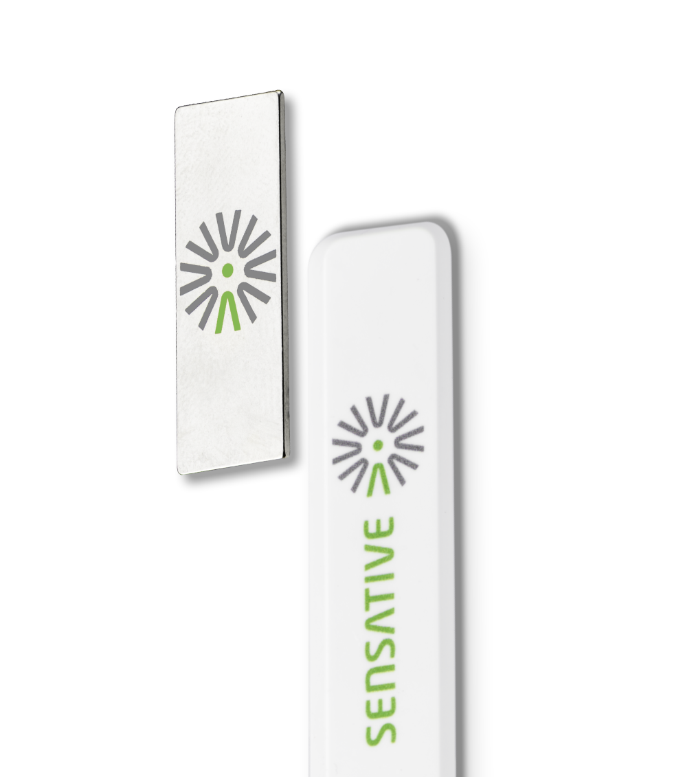
Strips Guard is an ultra-thin contact sensor and the thinnest magnet sensor in the world, detecting if your doors or windows are open or closed and featuring a design so sleek it disappears right into the architecture of any installation scenario.Strips Guard sends an alarm signal if it detects the opening of any door or window and due to its slim and discrete design, can also be placed in cabinets, on drawers or even behind artwork as an activity sensor. Its unique design allows it to be easily placed almost anywhere, generally in most places where other sensors simply cant fit.Strips Guard is an extremely reliable contact sensor. The unique design makes it easy to place nearly invisibly in your home to alert occupants of any open/close or activity event when connected to your Z-Wave smart home system.Strips 700 Series Guard can be used both indoors and out, and the integrated custom battery gives Strips an expected lifetime of 10+ years. For you, this means no hassles with changing or charging batteries in your Strips sensors for the lifetime of the product!Z-Wave Plus 700 series sensors bring a wealth of additional valued features such as longer range, low power consumption for extended battery life and SmartStart technology for instant enrolling. With SmartStart, device inclusion can be initiated automatically by simply removing the included magnets. The Z-Wave gateway then performs the inclusion process in the background without the need for user interaction. 700 Series provides a direct range of 100 meters, an improvement of 60 meters over the 500 series and also includes the industrys best S2 security, providing Strips Guard with the ultimate combination of features to securely protect your home.
Prepare for Installation / Reset
Please read the user manual before installing the product.
In order to include (add) a Z-Wave device to a network it must be in factory default state. Please make sure to reset the device into factory default. You can do this by performing an Exclusion operation as described below in the manual. Every Z-Wave controller is able to perform this operation however it is recommended to use the primary controller of the previous network to make sure the very device is excluded properly from this network.
Reset to factory default
This device also allows to be reset without any involvement of a Z-Wave controller. This procedure should only be used when the primary controller is inoperable.
1. Take the magnet and move it to the rounded edge and wait for the blink, then move the magnet away.
2. Repeat this 3 times, but on the 3rd repetition, keep the magnet at the rounded edge for 10 seconds. A long LED signal indicates success.
Safety Warning for Batteries
The product contains batteries. Please remove the batteries when the device is not used. Do not mix batteries of different charging level or different brands.
Installation
For good communication
Strips uses low power radio signals to communicate with your Z-Wave controller. For best results, please consider the following:
- Strips are designed to fit invisibly in most wood and plastic windows and doors.
- Strips should not be mounted directly on magnetic surfaces or encased within a metal structure as the range will be reduced.
- Strips range is up to 325 feet.
- Any non-battery Z-Wave device will act as a repeater to increase network reliability and range.
For good functionality in the door or window
- To place strips invisibly, you need a gap in your door or window frame with a minimum height of 3.5 mm.
- Strips may be mounted on the frame (recommended) and the magnet on the door/window, or vice versa.
- Open the door/window fully to check that the placement of Strips and the magnet does not interfere with hinges or locking mechanisms.
To correctly mount strips, please follow the steps below:
1. Make sure the surface is clean, dry and at least +10°C(+50°F). Use the included cloth to clean and prepare the surfaces.
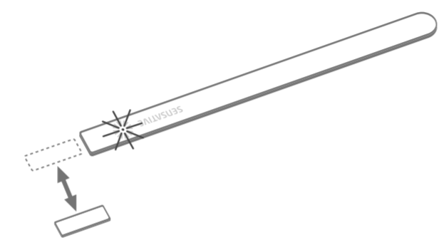
2. Remove the brown protective film from the small Strips test adhesive. This adhesive is used before the final placement, so it is easy to re-position Strips if needed.
3. Place strips where you want it mounted. Check the position by carefully closing the door/window and then opening it completely again.
4. Identify where the magnet should be placed (See picture below). Remove the protective film and place the magnet. Close and open again to validate that your Z-Wave controller detected the changes. Re-position if needed.
5. Check that the door/window can be fully closed and opened and that your Z-Wave controller detects the changes.
6. When you are satisfied, mark the exact position for strips. Remove it from its position, remove the long film protecting the adhesive backing, and place strips exactly as you marked.
7. Keep the spare magnet; it can be used to wake up, remove or reset Strips in the future. More guidance including instructional videos: www.sensative.com/strips
Magnet placement and sensor range
Check that the magnet can be placed so that it is less than 10 mm from Strips square end when the door/window is closed.
When the door/window is open, the magnet should be at least 30 mm away from Strips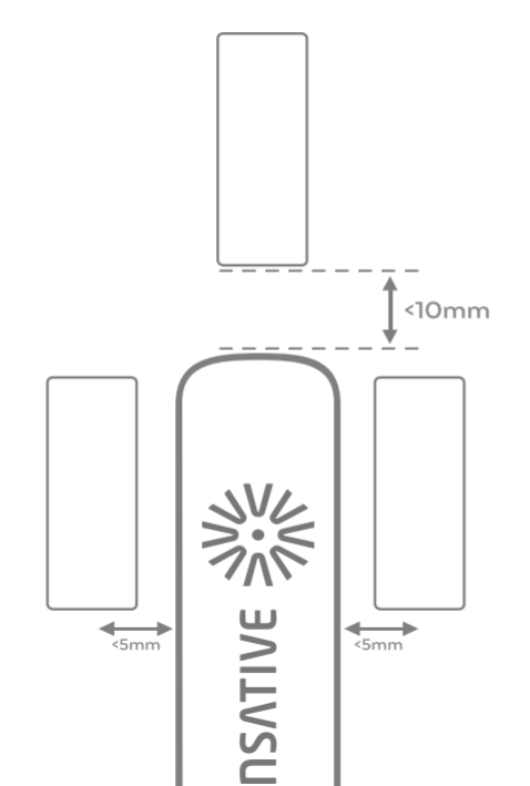
Installation Guidelines
https://sensative.com/download/strips-guard-detailed-mounting-guidelines/
Inclusion/Exclusion
On factory default the device does not belong to any Z-Wave network. The device needs to be added to an existing wireless network to communicate with the devices of this network. This process is called Inclusion.
Devices can also be removed from a network. This process is called Exclusion. Both processes are initiated by the primary controller of the Z-Wave network. This controller is turned into exclusion respective inclusion mode. Inclusion and Exclusion is then performed doing a special manual action right on the device.
Inclusion
1. Open your Z-Wave Controller application and start pairing mode.2. Remove both magnets from Strips.*
3. One long LED blink means Strips has been successfully added to your Z-Wave network.
*If you have previously removed the magnets from Strips, or need to re-add the device, performing a manual wake up will join the device when the controller is in pairing mode.
Exclusion
1. Take the magnet and move it to the rounded edge and wait for the blink, then move the magnet away.2. Repeat this 3 times. A final short blink will confirm that the user-command was successful.
Product Usage
To verify Strips is working properly
Move the squared magnet towards the square edge as shown in the picture. Check that your Z-Wave Controller displays the status correctly.
If your Z-Wave system doesn‘t respond, you may need to change strip‘s notification type from the controller.
LED Notification:
1 Short Blink
-User feedback during commands
-Successfully sent report
2 Short Blinks
- The indication when Strips are not added to a network
2 Long Blink
- A user command is successfully executed.
5 Short Blinks
- Error (e.g. communication with controller failed)
Communication to a Sleeping device (Wakeup)
This device is battery operated and turned into deep sleep state most of the time to save battery life time. Communication with the device is limited. In order to communicate with the device, a static controller C is needed in the network. This controller will maintain a mailbox for the battery operated devices and store commands that can not be received during deep sleep state. Without such a controller, communication may become impossible and/or the battery life time is significantly decreased.
This device will wakeup regularly and announce the wakeup
state by sending out a so called Wakeup Notification. The controller can then
empty the mailbox. Therefore, the device needs to be configured with the desired
wakeup interval and the node ID of the controller. If the device was included by
a static controller this controller will usually perform all necessary
configurations. The wakeup interval is a tradeoff between maximal battery
life time and the desired responses of the device. To wakeup the device please perform
the following action:
1. Take the magnet and move it to the rounded edge and wait for the blink, then move the magnet away.
2. Repeat this 3 times. A final short blink will confirm that the user-command was successful.
Quick trouble shooting
Here are a few hints for network installation if things dont work as expected.
- Make sure a device is in factory reset state before including. In doubt exclude before include.
- If inclusion still fails, check if both devices use the same frequency.
- Remove all dead devices from associations. Otherwise you will see severe delays.
- Never use sleeping battery devices without a central controller.
- Dont poll FLIRS devices.
- Make sure to have enough mains powered device to benefit from the meshing
Association - one device controls an other device
Z-Wave devices control other Z-Wave devices. The relationship between one device controlling another device is called association. In order to control a different device, the controlling device needs to maintain a list of devices that will receive controlling commands. These lists are called association groups and they are always related to certain events (e.g. button pressed, sensor triggers, ...). In case the event happens all devices stored in the respective association group will receive the same wireless command wireless command, typically a 'Basic Set' Command.
Association Groups:
| Group Number | Maximum Nodes | Description |
|---|---|---|
| 1 | 1 | Lifeline |
Configuration Parameters
Z-Wave products are supposed to work out of the box after inclusion, however certain configuration can adapt the function better to user needs or unlock further enhanced features.
IMPORTANT: Controllers may only allow configuring signed values. In order to set values in the range 128 ... 255 the value sent in the application shall be the desired value minus 256. For example: To set a parameter to 200 it may be needed to set a value of 200 minus 256 = minus 56. In case of a two byte value the same logic applies: Values greater than 32768 may needed to be given as negative values too.
Parameter 1: Notification type
Select the notification type for the door and window open or close events. Size: 1 Byte, Default Value: 1
| Setting | Description |
|---|---|
| 0 | Binary sensor report + Notification report (Access Control) |
| 1 | Notification report (Access Control) |
| 2 | Notification report (Home Security) |
Parameter 2: LED indication
Turn On or Off LED for specific event indications (ex. alarms). Size: 1 Byte, Default Value: 1
| Setting | Description |
|---|---|
| 0 | Turns off LED for door open events |
| 1 | On |
Parameter 15: Activate supervision
Activate Supervision command for onlyimportant alarm events or all events. Supervised commands require a confirmationfrom the gateway when a notification is received. Size: 1 Byte, Default Value: 1
| Setting | Description |
|---|---|
| 0 | Events sent with S2 Encapsulation only |
| 1 | Only Door Open Alarm Report (Events sent with S2 and supervision encapsulation) |
| 2 | Unsolicited reports (Door Open/Close, Tamper clear, Wake-up notification and Battery Report events sent with S2 and supervision encapsulation) |
Parameter 16: Supervision report wait time
Only used if parameter 22 is set to 1 (High security). The number of milliseconds to wait for a Supervision response when a Supervised message is sent. Size: 2 Byte, Default Value: 10000
| Setting | Description |
|---|---|
| 500 - 30000 | (ms) |
Parameter 17: No. of failed event retries
Only used if parameter 22 is set to 1 (High security). Number of retries when a confirmation is not received. Size: 1 Byte, Default Value: 1
| Setting | Description |
|---|---|
| 0 - 5 | 0 = No retry, 1 - 5 = Number of retries when a confirmation is not received. |
Parameter 18: Failed Event Retry Interval
Only used if parameter 22 is set to 1 (High security). The minimum number of seconds between retries. Size: 1 Byte, Default Value: 6
| Setting | Description |
|---|---|
| 1 - 60 | Min = 1 second, Max = 60 seconds |
Parameter 19: Heartbeat interval
Only used if parameter 22 is set to 1 (High security). Number of minutes between periodic battery reports (Heartbeats). Size: 1 Byte, Default Value: 70
| Setting | Description |
|---|---|
| 5 - 70 | (mins) - Accepts multiples of 5 mins. - Any arbitary value in between 5 and 70 will be rounded up to a multiple of 5 |
Parameter 22: Security Level
Select the level of security. Size: 1 Byte, Default Value: 0
| Setting | Description |
|---|---|
| 0 | : Standard (Forces parameter behaviour as follows: #16=1000, #17=Sensative standard**, #18=0, #19=Off, #21=Off** Retries with an incrementally longer period until reconnected |
| 1 | : High Security (Enables parameters 16-19, 21) |
Technical Data
| Dimensions | 195 mm |
| Weight | 20 gr |
| Hardware Platform | ZGM130 |
| EAN | 7350088520444 |
| IP Class | IP 44 |
| Voltage | 3V |
| Battery Type | 1 * Built-in 3.0 V LiMnO2 |
| Device Type | Notification Sensor |
| Network Operation | Reporting Sleeping Slave |
| Z-Wave Version | 7.13.3 |
| Certification ID | ZC12-20120144 |
| Z-Wave Product Id | 0x019A.0x0004.0x0004 |
| Firmware Updatable | Updatable by Consumer by RF |
| Color | White |
| Outdoor Use | ok |
| Frequency | Europe - 868,4 Mhz |
| Maximum transmission power | 5 mW |
Supported Command Classes
- Application Status
- Association Grp Info V3
- Association V2
- Battery
- Configuration V4
- Device Reset Locally
- Firmware Update Md V5
- Indicator V3
- Manufacturer Specific V2
- Multi Channel Association V3
- Notification V8
- Powerlevel
- Security 2
- Sensor Binary
- Supervision
- Transport Service V2
- Version V3
- Wake Up V2
- Zwaveplus Info V2
Explanation of Z-Wave specific terms
- Controller — is a Z-Wave device with capabilities to manage the network. Controllers are typically Gateways,Remote Controls or battery operated wall controllers.
- Slave — is a Z-Wave device without capabilities to manage the network. Slaves can be sensors, actuators and even remote controls.
- Primary Controller — is the central organizer of the network. It must be a controller. There can be only one primary controller in a Z-Wave network.
- Inclusion — is the process of adding new Z-Wave devices into a network.
- Exclusion — is the process of removing Z-Wave devices from the network.
- Association — is a control relationship between a controlling device and a controlled device.
- Wakeup Notification — is a special wireless message issued by a Z-Wave device to announces that is able to communicate.
- Node Information Frame — is a special wireless message issued by a Z-Wave device to announce its capabilities and functions.