Heatit (Thermo-Floor)
Heatit Z-Relay 25A
SKU: HEAE4512554


Quickstart
This is a
Clicking the inclusion button in the module
Important safety information
Please read this manual carefully. Failure to follow the recommendations in this manual may be dangerous or may violate the law. The manufacturer, importer, distributor and seller shall not be liable for any loss or damage resulting from failure to comply with the instructions in this manual or any other material. Use this equipment only for its intended purpose. Follow the disposal instructions. Do not dispose of electronic equipment or batteries in a fire or near open heat sources.Product Description
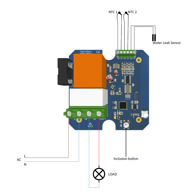
- The Heatit Z-Relay is a Z-Wave module housed in a water-resistant casing with 10 membrane cable entries.
- It features 1 relay output, 3 multi-purpose inputs, and a Z-Wave radio for wireless network interfacing.
- The module requires a 230V AC mains power supply.
- The relay output can be freely controlled via the Z-Wave network, suitable for controlling devices like valve actuators and stoves.
- Two inputs can be configured as digital or analog for NTC temperature sensors, while the third can function as a digital input or connect to a flood sensor.
- The module allows configuration of the status indicator LED on its circuit board.
Installation
Product Usage
Temperature inputs
Input 1 and 2 can be used as temperature inputs by connecting NTC sensors to the inputs. The type of NTC sensor can be configured by means of configuration parameters 3 and 4.A temperature offset can be configured for each of the inputs by means of configuration parameters 5 and 6.
Flood sensor input
Input 3 is a flood sensor input where it is possible to connect a simple flood sensor. The flood sensor can be left lying on the floor (on an electrically insulating surface), or attached to the floor or a wall. Designed for flood detection, it senses water and other electrically conductive liquids. The sensitivity of the sensor can be configured by means of configuration parameter 14.
It is possible for the flood input to directly control the Heatit Z-Relay output, either to turn the relay output ON or OFF when a flood is detected, or when no flood is detected, see configuration parameters 12 and 13.
Relay Output
The relay output is a high power "normally open" (NO) contact that can be used for several purposes. It is possible to control the relay from the Z-Wave network, or it can be controlled by the flood sensor input.
The Heatit Z-Relay monitors the current used by the load connected to the relay output. The energy that the load consumes is calculated by means of the measured current and the voltage entered in configuration parameter 15. Energy data is sent to the controller through the Z-Wave network. These data values that the controller is able to receive are: current (A), power (Watt), and the energy consumed over time (kWh).
| Reset to factory default | The Heatit Z-Relay can be factory reset by pressing the inclusion button in the module for at least 10 seconds. |
| Inclusion | Clicking the inclusion button in the module |
| Exclusion | Clicking the inclusion button in the module |
| NIF | XXXNIF |
| Wakeup | XXXWakeupDescription |
| Protection | XXXProtection |
| FirmwareUpdate | XXXFirmwareUpdate |
| SetAssociation | XXXSetAssociation |
Association Groups:
| Group Number | Maximum Nodes | Description |
|---|---|---|
| 1 | 5 | lifeline |
| 2 | 5 | Sensor Multilevel Report for input 1. |
| 3 | 5 | Sensor Multilevel Report for input 2. |
| 4 | 5 | Basic Report On / Off when the flood sensor detects a flood. |
| 5 | 5 | Basic Set On / Off when the flood sensor detects a flood |
| 6 | 5 | Notification Report when the flood sensor detects a flood. |
Configuration Parameters
Parameter 1: Status LED.
Configuration of the status LED.
Size: 1 Byte, Default Value: 1
| Setting | Description |
|---|---|
| 0 | LED turned off. |
| 1 | LED turned on. |
| 2 | LED flashing at 1 second intervals (½ Hz). |
| 3 | LED flashing at ½ second interval (1 Hz). |
Parameter 2: LED brightness level
Configure the percentage of light in the status LED, when the LED is turned on.
Size: 1 Byte, Default Value: 50
| Setting | Description |
|---|---|
| 1 - 100 | Brightness level of the LED |
Parameter 3: Thermistor type for input 1
Configures the thermistor type connected to input 1.
Size: 1 Byte, Default Value: 0
| Setting | Description |
|---|---|
| 0 | Input disabled. |
| 1 | 10K NTC |
Parameter 4: Thermistor type for input 2
Configures the thermistor type connected to input 2.
Size: 1 Byte, Default Value: 0
| Setting | Description |
|---|---|
| 0 | Input disabled. |
| 1 | 10K NTC |
Parameter 5: Temperature offset on input 1.
Configures a temperature offset that can be added to the measured temperature in order to get a more accurate measurement from the thermistor on input 1. Size: 1 Byte, Default Value: 0
| Setting | Description |
|---|
Parameter 6: Temperature offset on input 2.
Configures a temperature offset that can be added to the measured temperature in order to get a more accurate measurement from the thermistor on input 2. Size: 1 Byte, Default Value: 0
| Setting | Description |
|---|---|
| -40 - 40 | -4,0 – 4,0°C. |
Parameter 7: Time interval for reports sent about input 1.
Configures the time interval between when sensor reports are transmitted for input 1.
Size: 2 Byte, Default Value: 6
| Setting | Description |
|---|
Parameter 8: Time interval for reports sent about input 2.
Configures the time interval between when sensor reports are transmitted for input 2.
Size: 2 Byte, Default Value: 6
| Setting | Description |
|---|
Parameter 9: Time interval between notification reports for input 3.
Configures the time interval between when notification reports for flood input 3. Size: 2 Byte, Default Value: 6
| Setting | Description |
|---|---|
| 0 - 8640 | 0 – 86 400 seconds. |
Parameter 10: Time interval between meter reports.
Configures the time interval between when meter reports for reporting the energy (kWh) consumed by the load connected to the relay output.
Size: 2 Byte, Default Value: 2
| Setting | Description |
|---|---|
| 0 - 8640 | 0 – 86 400 seconds. |
Parameter 11: Flood steady timer.
Configures the time that the flood input (input 3) has to be steady before the state is accepted as a valid state.gures the time that the flood input (input 3) has to be steady before the state is accepted as a valid state.
Size: 1 Byte, Default Value: 6
| Setting | Description |
|---|---|
| 0 - 60 | 0 – 60 seconds. |
Parameter 12: Auto relay on.
Configures internal states that will cause the relay to be turned on.
Size: 1 Byte, Default Value: 1
| Setting | Description |
|---|---|
| 0 | Relay is not turned on automatically. |
| 1 | The relay is turned on when a flood is detected. |
| 2 | The relay is turned on when no flood is detected. |
Parameter 13: Auto relay off.
Configures internal states that will cause the relay to be turned off.
Size: 1 Byte, Default Value: 2
| Setting | Description |
|---|---|
| 0 | Relay is not turned off automatically. |
| 1 | The relay is turned off when a flood is detected. |
| 2 | The relay is turned off when no flood is detected. |
Parameter 14: Flood detection threshold.
Configures the threshold for input 3 that will cause a flood to be detected.
Size: 2 Byte, Default Value: 2048
| Setting | Description |
|---|---|
| 0 - 4095 | Low value means a low detection threshold, high value will cause the input to be more sensitive. |
Parameter 15: Voltage
Configures the value used for power calculation, as only the current for the load on the relay output is measured.
Size: 1 Byte, Default Value: 220
| Setting | Description |
|---|---|
| 0 - 250 | Volt |
Parameter 18: Size of load connected on the relay output.
Configures a constant value that will be used in power metering when this value is different from 0. This value specifies the actual load in Watt used for power metering. Size: 2 Byte, Default Value: 0
| Setting | Description |
|---|---|
| 0 - 6000 | Watt |
Technical Data
| Dimensions | 100 x 100 x 46 mm |
| Weight | 223 gr |
| Hardware Platform | ZM5101 |
| EAN | 7071236014126 |
| IP Class | IP 55 |
| Voltage | 230 V |
| Load | 25 A |
| Device Type | Relay |
| Generic Device Class | Binary Switch |
| Firmware Version | 00.08 |
| Z-Wave Version | 04.3d |
| Z-Wave Product Id | 0x019b.0x0003.0x0208 |
| Frequency | Europe - 868,4 Mhz |
| Maximum transmission power | 5 mW |